


Installation Manual 17
I/O Wiring – Model 2400S Analog Transmitters
Power Supply I/O Wiring – DP and DNI/O Wiring – ANBefore You Begin
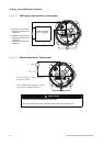
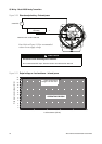
Figure 3-8 Frequency output wiring – External power
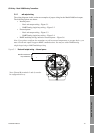
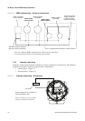
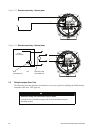
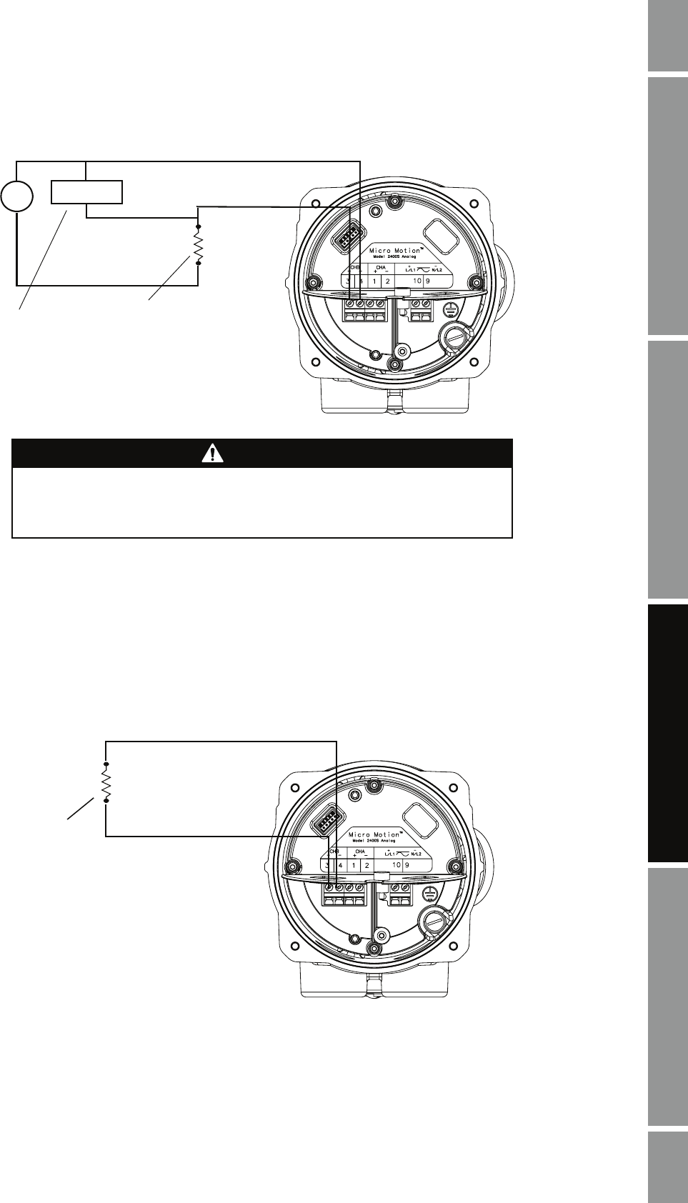
3.4.3 Discrete output wiring
Discrete output wiring depends on whether you will use internal or external power. The following
diagrams are examples of proper wiring for these configurations:
• Internal power – Figure 3-9
• External power – Figure 3-10
Figure 3-9 Discrete output wiring – Internal power
–
+
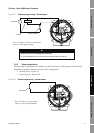
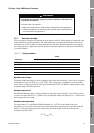
Note: See Figure 3-12 for recommended
resistor versus supply voltage.
000042
Counter
Pull-up resistor
3–36 VDC
+
–
CAUTION
Excessive current will damage the transmitter.
Do not exceed 36 VDC input. Terminal current must be less than 500 mA.
Total load
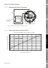
Note: See Figure 3-11 for output
voltage versus load information.
+
–