


Installation Manual 23
I/O Wiring – Model 2400S Analog Transmitters
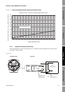
Power Supply I/O Wiring – DP and DNI/O Wiring – ANBefore You Begin
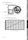
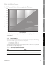
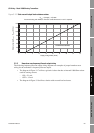
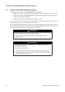
Figure 3-16 Safe area mA output load resistance values
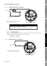
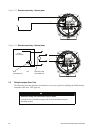
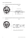
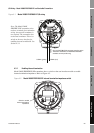
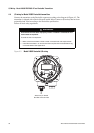
3.5.3 Hazardous area frequency/discrete output wiring
The following frequency/discrete output wiring diagrams are examples of proper hazardous area
wiring for the transmitter’s frequency/discrete output:
• The diagram in Figure 3-17 utilizes a galvanic isolator that has an internal 1000 Ohm resistor
used for sensing current:
- ON > 2.1 mA
- OFF < 1.2 mA
• The diagram in Figure 3-18 utilizes a barrier with external load resistance.
0
200
400
600
800
1000
1200
1400
0 4 8 12 16 20 24 28 32 36
Supply voltage VDC (Volts)
External resistor R
load
+ R
barrier
(Ohms)
R
max
= (Vsupply – 4)/0.022
If communicating with HART, a minimum of 250 Ohms and 17.5 V is required
OPERATING REGION