


16 Micro Motion
®
Model 2400S Transmitters
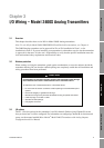
I/O Wiring – Model 2400S Analog Transmitters
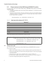
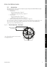
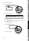
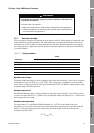
Figure 3-6 HART multidrop wiring – Internal or external power
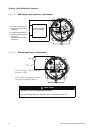
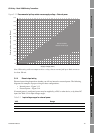
3.4.2 Frequency output wiring
Frequency output wiring depends on whether you will use internal or external power. The following
diagrams are examples of proper wiring for these configurations:
• Internal power – Figure 3-7
• External power – Figure 3-8
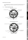
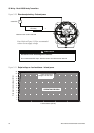
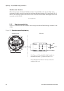
Figure 3-7 Frequency output wiring – Internal power
HART-compatible
host or controller
HART-compatible
transmitter
SMART FAMILY
™
transmitter
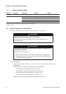
Note: For optimum HART communication, make sure the output loop
is single-point-grounded to an instrument-grade ground.
24 VDC loop power
supply required for
HART 4–20 mA
passive transmitters
600 Ohm maximum resistance
250 Ohm minimum resistance
Model 2400S
External power
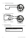
Model 2400S
Internal power
Counter
000042
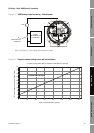
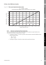
Note: See Figure 3-11 for output
voltage versus load resistance.
+
–
Output voltage level is +24 VDC ±3%
with high resistance load.