


Page 5
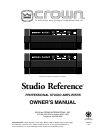
Studio Reference
II
II
I
&
IIII
IIII
II
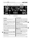
Professional Studio Amplifiers
ILLUSTRATIONS
1.1
Studio Reference
I Amplifier ........................................... 6
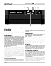
2.1 Front Facilities ................................................................. 8
2.2 Rear Facilities ................................................................. 9
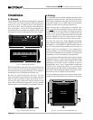
3.1 Mounting Dimensions.................................................... 10
3.2 Removing an End Cap .................................................. 10
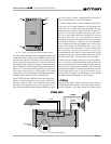
3.3 Top View of a Rack-Mounted Unit.................................. 10
3.4 Proper Air Flow with a Rack-Mounted Blower ................ 11
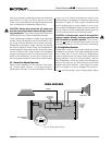
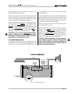
3.5 Stereo Wiring ................................................................ 11
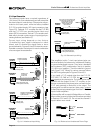
3.6 Bridge-Mono Wiring ...................................................... 12
3.7 Parallel-Mono Wiring ..................................................... 13
3.8 Unbalanced Input Wiring............................................... 14
3.9 Balanced Input Wiring ................................................... 14
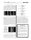
3.10 Balanced and Unbalanced Phone Plugs ....................... 14
3.11 Subsonic Filter Capacitors ............................................ 15
3.12 Unbalanced RF Filters ................................................... 15
3.13 Balanced RF Filters ....................................................... 15
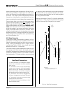
3.14 Wire Size Nomograph ................................................... 16
3.15 Inductive Load (Transformer) Network ........................... 17
3.16 Loudspeaker Fuse Nomograph ..................................... 18
4.1 Indicators...................................................................... 19
4.2
Studio Reference
Indicator States.................................. 20
4.3 Removing a Handle ...................................................... 22
4.4 Meter Switches ............................................................. 23
4.5 Input Sensitivity and Ground Lift Switches ..................... 23
5.1 Circuit Block Diagram ................................................... 25
6.1
Studio Reference
I Minimum Power Matrix .................... 29
6.2
Studio Reference
II Minimum Power Matrix .................. 30
6.3
Studio Reference
I Maximum Power Matrix ................... 31
6.4
Studio Reference
II Maximum Power Matrix ................. 32
6.5 Typical Frequency Response ........................................ 33
6.6 Typical Damping Factor ................................................ 33
6.7 Typical Output Impedance ............................................ 33
6.8 Typical Phase Response ............................................... 34
6.9 Typical Common Mode Rejection .................................. 34
6.10 Typical Crosstalk........................................................... 35
7.1
Studio Reference
I Power Draw, Current Draw and
Thermal Dissipation at Various Duty Cycles ................... 36
7.2
Studio Reference
II Power Draw, Current Draw and
Thermal Dissipation at Various Duty Cycles ................... 37
8.1 Installing a
P.I.P.
Module ............................................... 38