


Page 17
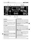
Studio Reference
II
II
I
&
IIII
IIII
II
Professional Studio Amplifiers
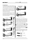
amplifiers share a common cable tray or jacket,
use tie-wraps to bundle individual conductors so
the wires for each loudspeaker are kept close
together. (Do not bundle wires from different
amplifiers.) This reduces the chance of conduc-
tors acting like antennas to transmit or receive the
high frequencies that can cause oscillation.
2. Avoid using shielded loudspeaker cable.
3. Never tie together input and output grounds.
4. Never tie together the output of different amplifiers.
5. Keep output cables separated from input cables.
6. Install a low-pass filter in series with each input
(see Section 3.3.4).
7. Install the input wiring according to the instruc-
tions in Section 3.3.4.
Another problem to avoid is the presence of large
subsonic currents when primarily inductive loads are
used. Examples of inductive loads are 70-volt step-up
transformers and electrostatic loudspeakers.
Inductive loads can appear as a short circuit at low fre-
quencies. This can cause the amplifier to produce
large low-frequency currents and activate its protec-
tion circuitry. Always take the precaution of installing a
high-pass filter in series with the amplifier’s input when
inductive loads are used. A three-pole, 18 dB per oc-
tave filter with a –3 dB frequency of 50 Hz is recom-
mended (some applications may benefit from an even
higher –3 dB frequency). Such a filter is described with
the subsonic frequency problems in Section 3.3.4.
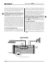
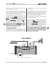
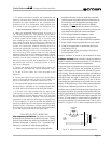
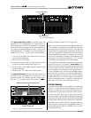
Another way to protect inductive loads from large low-
frequency currents and prevent the amplifier from pre-
maturely activating its protective systems is to parallel
a 590 to 708 mF nonpolarized motor start capacitor and
4-ohm, 20-watt resistor in series with the amplifier out-
put and the positive (+) transformer lead. This circuit is
shown in Figure 3.15. It uses components that are
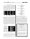
1. For loads connected in parallel, use the equation that
follows to calculate each channel’s total load resistance.
Substitute the rated impedance of the connected loud-
speakers for the Zs in the equation. When finished, mark
your answer on the nomograph’s “Load Resistance” line.
Total Load Resistance in Ohms = (
1
¦
Z
1
+
1
¦
Z
2
+
1
¦
Z
3
…)
–1
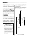
2. Select an acceptable damping factor and mark it on
the “Damping Factor” line. Your amplifier can provide an
phenomenal damping factor of 20,000 from 10 to 200 Hz
in Stereo mode with an 8 ohm load. In contrast, most
other amplifiers have a damping factor rating of 200 or
less. Higher damping factors yield lower distortion and
greater motion control over the loudspeakers. To give you
a basis for comparison, effective damping factors for
commercial applications typically run between 50 and
100. Higher damping factors may be desirable for live
sound, but long cable lengths often limit the highest
damping factor that can be achieved practically. (Under
these circumstances, Crown’s
IQ System
is often used so
amplifiers can be easily monitored and controlled when
they are located very near the loudspeakers.) In record-
ing studios and home hi-fi, a damping factor of 500 or
more is very desirable.
3. Draw a line through the two points with a pencil, and
continue until it intersects the “Source Resistance” line.
4. On the “2-Cond. Cable” line, mark the length of the
cable run.
5. Draw a pencil line from the mark on the “Source Resis-
tance” line through the mark on the “2-Cond. Cable” line,
and on to intersect the “Annealed Copper Wire” line.
6. The required wire gauge for the selected wire length and
damping factor is the value on the “Annealed Copper Wire”
line.
Note: Wire size increases as the AWG gets smaller
.
7. If the size of the cable exceeds what you want to use,
(1) find a way to use shorter cables, like using the
IQ Sys-
tem
, (2) settle for a lower damping factor, or (3) use more
than one cable for each line. Options 1 and 2 will require the
substitution of new values for cable length or damping factor
in the nomograph. For option 3, estimate the effective wire
gauge by subtracting 3 from the apparent wire gauge every
time the number of conductors of equal gauge is doubled.
So, if #10 wire is too large, two #13 wires can be substituted,
or four #16 wires can be used for the same effect.
SOLVING OUTPUT PROBLEMS
High frequency oscillations can cause your amplifier
to prematurely activate its protection circuitry. The ef-
fects of this problem are similar to the effects of the RF
problem described in Section 3.3.4. To prevent high-
frequency oscillations, follow these guidelines:
1. When using long cable runs, or when different
Fig. 3.15 Inductive Load (Transformer) Network
4-ohm, 20-watt
Resistor
590 to 708 µf Capacitor
120 VAC, N.P.
+
–
Inductive
Load
+
–
From
Amplifier
Output