


Page 20
Studio Reference
II
II
I
&
IIII
IIII
II
Professional Studio Amplifiers
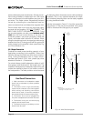
As dynamic range meters they show each channel’s
ratio of peak-to-average power in dB. The dynamic
range may be low for sources like AM/FM radio or low-
quality recordings. Other sources like live music or
high-quality recordings may be much higher. As out-
put level meters they show how high the output levels
are in dB relative to full power. At 0 dB, the unit is deliv-
ering full standard 1 kHz power (see Section 6).
4.3 Protection Systems
Studio Reference
amplifiers provide extensive protec-
tion and diagnostics capabilities. Protection systems
include
ODEP
, standby mode, an AC circuit breaker
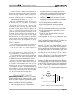
The green signal presence indicators flash synchro-
nously with the amplifier’s output signal. The signal de-
tector is connected to the signal path after the input
gain stages and level controls, so a flashing indicator
tells you that there is audio in and out of the amplifier.
Note: The signal presence indicators may not report
signal presence if the output signal level is too low.
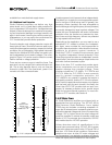
The dynamic range /level meters are five-segment
output meters that can be set to monitor either the dy-
namic range or the level of the output signal. They are
factory-set to show dynamic range. A switch located
behind the front panel is used to select the meter dis-
play mode (see Section 4.4 for complete instructions).
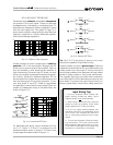
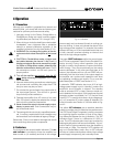
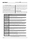
Fig. 4.2 Studio Reference Indicator States
There is no power to the amplifier. Possible reasons: (1) The amplifier’s enable switch is off. (2) The
amplifier is not plugged into the power receptacle. (3) The AC mains circuit breaker has been tripped.
(4) The amplifier’s circuit breaker has been tripped.
Indicator Status Amplifier Condition
Normal operation for a channel with NO output. Possible reasons: (1) There is no input signal.
(2) The input signal level is very low. (3) The channel’s level control is turned down.
Normal operation for a channel with audio output. The ODEP indicator will remain at full intensity
to show that there is reserve thermal-dynamic energy and the signal presence indicator will flash to
show that there is audio output.
The channel’s output is exceeding 0.05% distortion. The input signal level is too high, and IOC is
reporting either an input overload or output clipping.
The amplifier is in standby mode. Possible reasons: (1) The amplifier has just been turned on and
is still in the four second turn-on delay. (2) A P.I.P. module such as an IQ-P.I.P. has turned off the
channel’s high-voltage supply. (3) The DC/low-frequency protection circuitry has been activated.
(4) The fault protection circuitry has been activated. (5) The transformer thermal protection circuitry
has been activated. (6) The overvoltage protection circuitry has been activated.
ODEP limiting has been activated. Possible reasons: (1) The amplifier’s air filter is blocked and needs
to be cleaned. (2) There is insufficient cooling because of inadequate air flow or air that is too hot.
(3) The load impedance for the channel is too low because the output is shorted or the amplifier is
driving too many loudspeakers for the selected stereo/mono mode. (4) The amplifier channel is
continuously being driven to very high output levels.
ODEP limiting is about to begin or has just ended. Possible reasons: (1) The amplifier’s air filter is
blocked and needs to be cleaned. (2) There is insufficient cooling because of inadequate air flow or air
that is too hot. (3) The load impedance for the channel is too low because the output is shorted or the
amplifier is driving too many loudspeakers for the selected stereo/mono mode. (4) The amplifier
channel is continuously being driven to very high output levels.
OR
Channel 2 only: The amplifier is in Parallel-Mono mode and has output. The channel 2 IOC indi-
cator always turns on when the amplifier’s stereo/mono switch is moved to the Parallel-Mono position.
IOCODEP SIGNAL
OFF OFF OFF
IOCODEP SIGNAL
ON OFF OFF
IOCODEP SIGNAL
ON OFF Active
Channel 2 only: The amplifier is in Parallel-Mono mode with no output. The channel 2 IOC indi-
cator always turns on when the amplifier’s stereo/mono switch is moved to the Parallel-Mono position.
IOCODEP SIGNAL
ON ON OFF
IOCODEP SIGNAL
ON ON Active
IOCODEP SIGNAL
OFF ON OFF
IOCODEP SIGNAL
OFF OFF Active
IOCODEP SIGNAL
OFF ON Active