


Page 13
Studio Reference
II
II
I
&
IIII
IIII
II
Professional Studio Amplifiers
greatly degraded. Also, turn down the channel 2 level
control (fully counterclockwise).
Note: The channel 2 input and level control are not de-
feated in Bridge-Mono mode. Any signal feeding chan-
nel 2 will work against the channel 1 signal, and usually
results in distortion and inefficient operation.
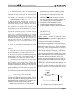
Connect the load across the two red (+) binding posts
(see Figure 3.6). The positive (+) loudspeaker lead
connects to the red channel 1 binding post, and the
negative (–) or ground lead from the loudspeaker con-
nects to the red channel 2 binding post. Do not con-
nect the black binding posts (–). Also, the load must be
balanced (neither side shorted to ground).
CAUTION: Only connect balanced equipment
(meters, switches, etc.) to the Bridge-Mono output.
Both sides of the line must be isolated from the in-
put grounds or oscillations may occur.
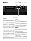
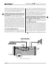
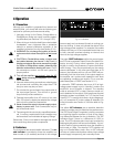
3.3.3 Parallel-Mono Operation
Parallel-Mono mode is used to drive loads with a total
impedance of less than 4 ohms (see Bridge-Mono if the
load is 4 ohms or more). Wiring for Parallel-Mono mode
Reference
STUDIO
CH-2 CH-1
PUSHPUSH
FX
STUDIO REFERENCE
AMPLIFIER
MIXER
LOUDSPEAKER
–
+
CHANNEL 1
THE CHANNEL 2
INPUTS ARE
NOT USED
ADD A 14 GAUGE
OR LARGER
JUMPER BETWEEN
THE CHANNEL 1
AND 2 RED (+)
BINDING POSTS
CAUTION: TURN OFF AMPLIFIER
BEFORE CHANGING THIS SWITCH!
STEREO
BRIDGE
MONO
PARALLEL
MONO
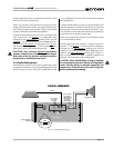
PARALLEL-MONO MODE
Fig. 3.7 Parallel-Mono Wiring
is very different from the other modes and requires
special attention.
To select Parallel-Mono mode, turn off the amplifier and
slide the stereo/mono switch to the left (as you face the
back panel). Connect the input signal to channel 1 only.
The channel 2 input and level control are bypassed in
this mode, so they should not be used.
Note: It is normal for the channel 2 IOC indicator to stay
on in Parallel-Mono mode.
Connect the load to the channel 1 output as shown in
Figure 3.7. The positive (+) lead from the loudspeaker
connects to the red channel 1 binding post, and the
negative (–) or ground lead from the loudspeaker con-
nects to the black channel 1 binding post. Finally, in-
stall a jumper wire of at least 14 gauge between the
channel 1 and channel 2 red binding posts.
CAUTION: When Parallel-Mono wiring is installed,
do not attempt to operate in Stereo or Bridge-Mono
mode until the wiring is removed (especially the
jumper wire). Failure to do so will result in high dis-
tortion and excessive heating.