


Page 23
Studio Reference
II
II
I
&
IIII
IIII
II
Professional Studio Amplifiers
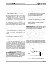
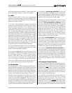
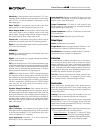
Fig. 4.5 Input Sensitivity and Ground Lift Switches
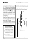
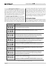
Fig. 4.4 Meter Switches
®
METER ON/OFF SWITCH
ONOFF
DYNAMIC RANGEOUTPUT LEVEL
METER MODE SWITCH
0
.
7
7
5
V
1.4 V
SENSITIVITY SWITCH INSIDE ACCESS HOLE
26
d
B
UNBALANCED
INPUT WIRING
BALANCED
INPUT WIRING
CH-2 CH-1
+
–
TIP
RING
SLEEVE
GND
INPUT GROUND LIFT
LIFT
+
TIP
SLEEVE
GND
(AFFECTS PHONE INPUTS ONLY.)
(MONO)
This amplifier is equipped with a selectable input sensitivity. Remove the P.I.P. module to access the sensitivity switch.
GROUND LIFT SWITCH
The input sensitivity switch is located inside the
amplifier’s
P.I.P.
compartment. It is factory-set to a
fixed voltage gain of 26 dB. For standard 1 kHz power
into 8 ohms, this is equivalent to an input sensitivity of
4.0 volts for the
Studio Reference
I and 2.7 volts for the
Studio Reference
II. If needed, it can be switched to a
sensitivity of 0.775 or 1.4 volts. Here is the procedure:
1. Turn off the amplifier and disconnect the power
cord from the receptacle.
2. Remove the
P.I.P.
module.
3. Locate the access hole for the sensitivity switch
inside the chassis opening (see Figure 4.5).
4. Set the switch to the desired position noted on the
access hole label.
5. Replace the
P.I.P.
module and restore power.
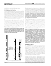
The ground lift switch located on the back panel can
provide isolation between the phone jack input
grounds and the AC (chassis) ground. It does not af-
fect the
P.I.P.
module’s input connectors. Slide the
switch to the left to isolate or “lift” the grounds.
Note: The noninverted and inverted signal lines for the
P.I.P. module are connected in parallel with the corre-
sponding lines of the phone jack inputs. The input sig-
nal grounds are not paralleled. Specifically, XLR pins 2
and 3 are connected in parallel with the tip and ring of
the corresponding phone jack. However, pin 1 of the
XLR is not connected in parallel with the sleeve of the
phone jack. This makes it possible for a P.I.P. module
to handle its own signal grounds independently.
The amplifier’s circuit breaker protects the power sup-
plies from overload. The breaker’s reset switch is lo-
cated on the back panel. Facing the back panel, move
the reset switch the left to disconnect power to the
power supplies, or to the right to reconnect power. If
the circuit breaker trips, the front panel enable indica-
tor will turn off. If this occurs, turn off the enable switch,
flip the reset switch to the right (on), and then turn the
enable switch back on. If it trips again or the amplifier
does not operate properly, contact an authorized ser-
vice center or Crown’s Technical Support Group.
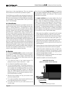
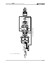
4.5 Filter Cleaning
A dust filter is provided on the amplifier’s air intake (see
Figure 2.1). If this filter becomes clogged, the unit will
not cool as efficiently as it should and high heat sink
temperatures may produce lower-than-normal output.
To clean the filter, gently pull it away from the front
panel and wash it with mild dishwashing detergent and
warm water. Be sure the filter is dry before you reinstall
it. Replacement filters may be ordered from the factory.
Dust filters are not 100% efficient—long term this may
require heat sink cleaning by a qualified technician. In-
ternal cleaning information is available from our Tech-
nical Support Group.