


Page 19
Studio Reference
II
II
I
&
IIII
IIII
II
Professional Studio Amplifiers
4 Operation
4.1 Precautions
Although your amplifier is protected from internal and
external faults, you should still take the following pre-
cautions for optimum performance and safety:
1. Improper wiring for the Stereo, Bridge-Mono or
Parallel-Mono modes can result in serious operat-
ing difficulties (see Sections 3.3.1 through 3.3.3).
2. When driving an inductive load like an electrostatic
loudspeaker, use a high-pass filter or protective
network to prevent premature activation of the
amplifier’s protection circuitry (see Section 3.3.4).
3. WARNING: Do not change the position of the ste-
reo/mono switch unless the amplifier is first turned
off.
4. CAUTION: In Parallel-Mono mode, a jumper must
be installed between the channel 1 and 2 red (+)
binding post outputs. Be sure to remove this jumper
for Stereo or Bridge-Mono modes, otherwise high
distortion and excessive heating will occur. Check
the stereo/mono switch on the back panel for
proper position.
5. Turn off the amplifier and unplug it from the AC
mains before removing the amplifier’s
P.I.P.
mod-
ule or dust filter.
6. Use care when making connections, selecting sig-
nal sources and controlling the output level. The
load you save may be your own!
7. Do not short the ground lead of an output cable to
the input signal ground. This will form a ground
loop and may cause oscillations.
8. Operate the amplifier from AC mains of not more
than 10% above or below the selected line voltage
and only at the rated line frequencies.
9. Never connect the output to a power supply output,
battery or power main. Such connections may re-
sult in electrical shock.
10. Tampering with the circuitry by unqualified person-
nel, or making unauthorized circuit changes may
be hazardous and invalidates all agency listings.
Remember: Crown is not liable for damage that results
from overdriving other system components.
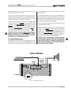
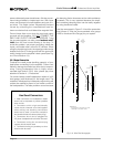
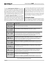
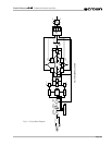
4.2 Indicators
The front panel has several helpful indicators. The en-
able indicator is provided to show the amplifier has
been turned on (or enabled) and that its low-voltage
Fig. 4.1 Indicators
power supply and on-demand forced air cooling sys-
tem are working. It does not indicate the status of the
high-voltage power supplies. For example, the enable
indicator will stay on in the improbable event that one
or both channels overheat causing an internal shut
down of the high
voltage supplies.
The green
ODEP
indicators confirm the normal opera-
tion of Crown’s patented Output Device Emulation Pro-
tection circuitry. During normal operation, they glow
brightly to confirm the presence of reserve thermody-
namic energy. They dim proportionally as the energy
reserve decreases. In the rare event that there is no
reserve, the indicators will turn off and
ODEP
will pro-
portionally limit the drive level of the output stages so
the amplifier can continue safe operation even when
the operating conditions are severe. (For a more de-
tailed description of
ODEP
, see Section 4.3.1.)
A channel’s
ODEP
indicator also turns off if its high-
voltage power supply is put in “standby” mode or the
amplifier’s circuit breaker is tripped. The standby
mode is activated if DC or heavy common-mode cur-
rent is detected in the output, if the transformer thermal
protection system is activated, if a
P.I.P.
like the
Smart
Amp
IQ-P.I.P. is used to shut down a high-voltage sup-
ply, or if excessive AC mains voltage is detected. For
more information see Section 4.3 and the table in Fig-
ure 4.2.
The yellow
IOC
indicators act as sensitive distortion
meters to provide
proof of distortion-free performance
.
The
IOC
(Input/Output Comparator) circuitry compares
the incoming signal’s waveform to that of the output.
Any difference between the two is distortion. The
IOC
indicators flash if there is a difference of 0.05% or
more. The
IOC
indicators also show input overload by
flashing brightly with a half-second hold delay. It is nor-
mal for them to light momentarily when the amplifier is
first turned on.
Note: The channel 2 IOC indicator will
stay on in Parallel-Mono mode.
Also, an IOC indicator
will stay on in abnormal situations where a high-voltage
power supply is temporarily put in standby mode.