


Chapter 1: Crown Amplifi ers In-Depth 9
Amplifi er Application Guide
1.2.2 Solving Input
Problems
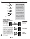
Infrasonic (Subaudible)
Frequencies
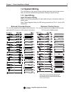
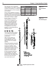
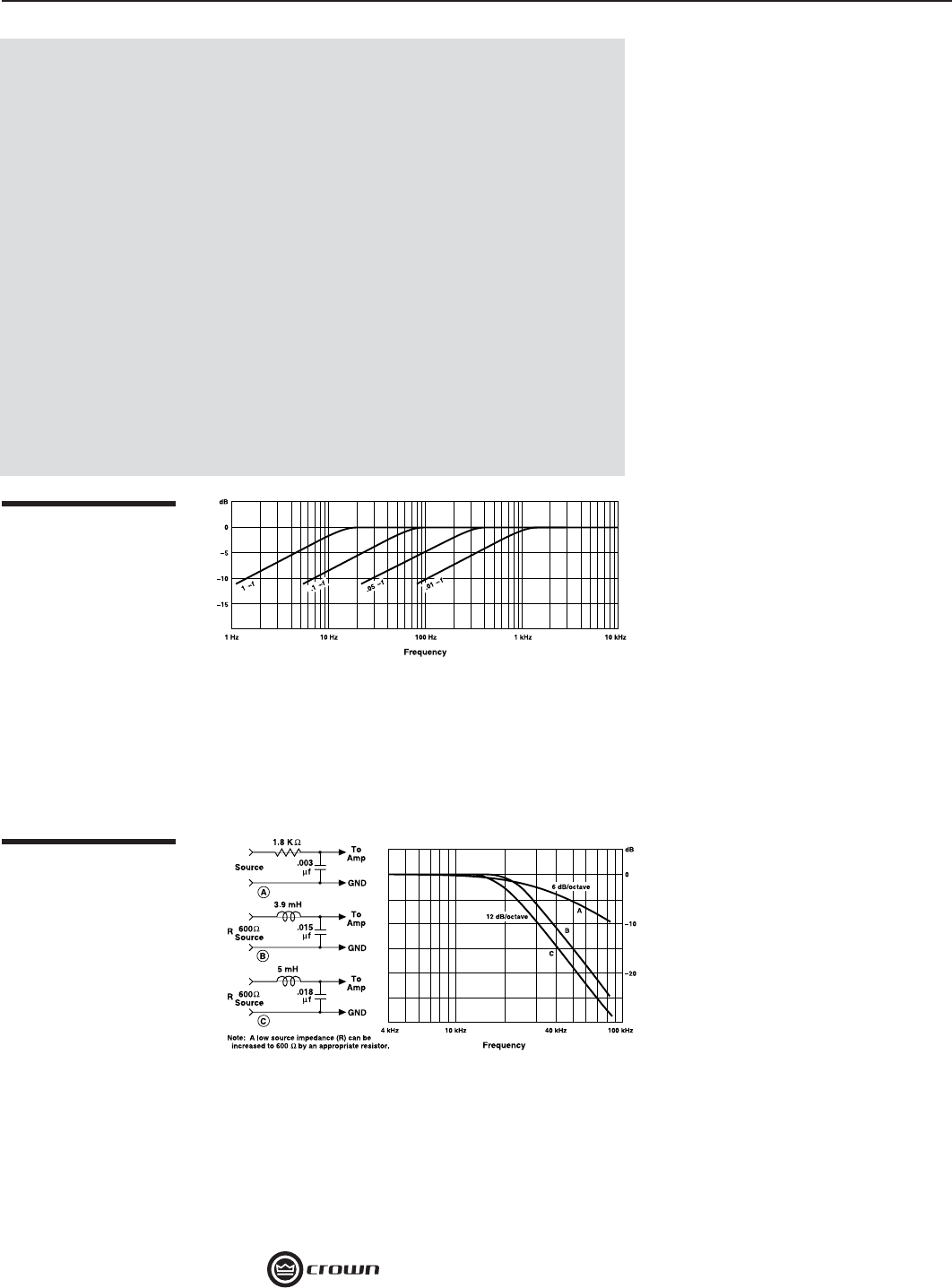
Sometimes large infrasonic (sub-
audible) frequencies are present in
the input signal. These can damage
loudspeakers by overloading or
overheating them. To attenuate such
frequencies, place a capacitor in
series with the input signal line. The
graph in Figure 1.3 shows some
capacitor values and how they affect
the frequency response. Use only
low-leakage paper, mylar or tantalum
capacitors.
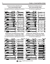
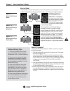
Radio Frequencies (RF)
Another problem to avoid is the
presence of large levels of radio
frequencies or RF in the input signal.
Although high RF levels may not
pose a threat to the amplifi er, they
can burn out tweeters or other loads
that are sensitive to high frequen-
cies. Extremely high RF levels can
also cause your amplifi er to prema-
turely activate its protection circuitry,
resulting in ineffi cient operation. RF
can be introduced into the signal
chain from many sources such as
local radio stations, tape recorder bias and digital signal processors (DSP). To prevent high
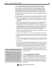
levels of input RF, install an appropriate low-pass fi lter in series with the input signal.
Some examples of unbalanced wiring for low-pass fi lters are shown in Figure 1.4.
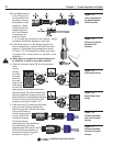
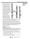
For balanced input wiring use one of the examples in Figure 1.5. Filters A, B and C correspond
to the unbalanced fi lters above. Filter D also incorporates the infrasonic fi lter described previ-
ously.
Hum and Buzz
If you have noticeable hum or buzz
in your system, you may want to
check your cable connections to
see if the unwanted noise is being
introduced via a ground loop. To
determine the proper wiring, fi rst
check whether the output from
your source is unbalanced or bal-
anced (if you don’t know, refer to
the unit’s back panel or Operation
Manual). Next, determine if the
source’s power cable is fl oating
(ungrounded, 2-prong) or grounded (3-prong). Finally, if the source in unbalanced, check the
type of wiring: twin-lead or single coax. Once you have determined the wiring scheme and
cable type, refer to the applicable wiring diagram in Section 1.2.1.
1. For all input connectivity, use
shielded wire only. Cables with a foil
wrap shield or a high-density braid
are superior. Cables with a stranded
spiral shield, although very fl exible,
will break down over time and cause
noise problems.
2. Try to avoid using unbalanced
lines with professional equipment. If
you have no choice, keep the cables
as short as possible (see “Balanced
vs. Unbalanced” on the next page).
3. To minimize hum and crosstalk,
avoid running low-level input cables,
high-level output wires and AC power
feeds in the same path. Try to run
differing signal-cable paths at 90°
to one another. If you must use a
common path for all cables, use
a star-quad cable for the low-level
signals.
4. Before changing input connec-
tors or wiring, turn the amplifi er level
controls all the way down (counter-
clockwise).
5. Before changing output connec-
tions, turn the amplifi er level down
and the AC power off to minimize the
chance of short-circuiting the output.
Input Wiring Tips
Figure 1.3
Subsonic Filter Capaci-
tor Values
Figure 1.4
Unbalanced RFI Filters