


12 Chapter 1: Crown Amplifi ers In-Depth
Amplifi er Application Guide
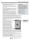
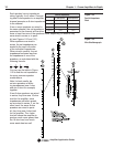
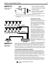
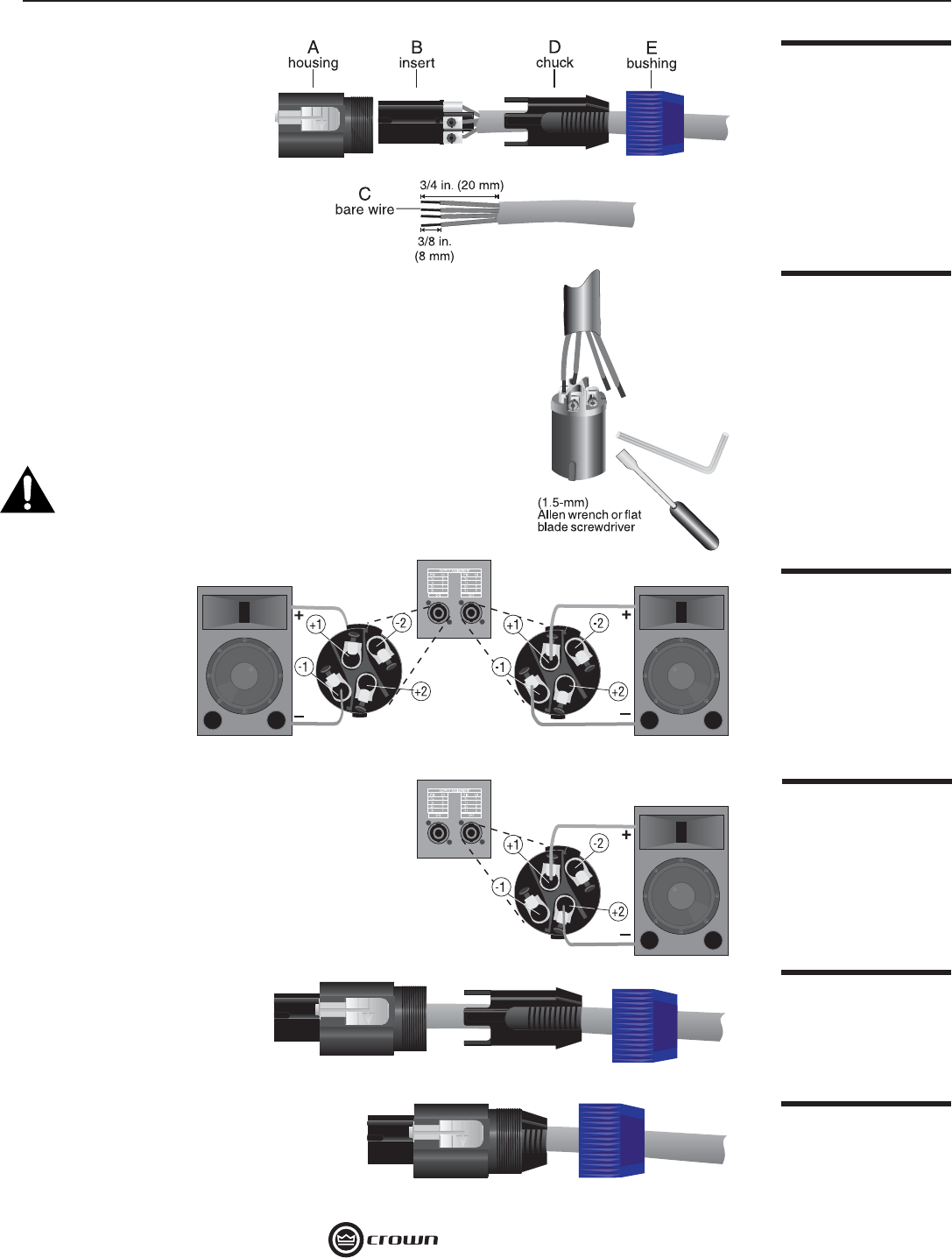
3b. If the Mode switch is
in the “Stereo” posi-
tion (for stereo con-
fi guration), connect
the positive (+) and
negative (–) leads
of each wire to the
appropriate Chan-
nel 1 and Channel
2 connectors as
shown in Figure
1.14. You may use all 4 poles of the Channel 1 output
connector to feed both speakers, if you wish.
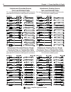
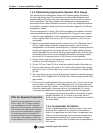
3c. If the Mode switch is in the “Bridge” position (for
mono confi guration), connect the load across the
positive (+) terminals of the connector as shown
in Figure 1.15. For Bridge-Mono Mode, non-invert-
ing output, Ch1+ is the positive (+) and Ch2+ is the
negative (–).
3d. Never short or parallel the output channels of
an amplifi er to itself or any other amplifi er.
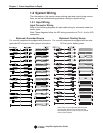
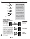
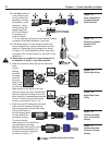
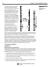
4. Slide the connector insert (B) into the connector
hous-
ing (A),
making
sure that
the large
notch on
the outer
edge of the
insert lines
up with the
large groove on the inside of the con-
nector housing. The insert should slide
easily through the housing and out the
other side until it extends approximately
3/4-inch (19-mm) from the end of the
housing, as shown in Figure 1.16.
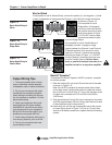
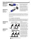
5. Slide the chuck (D) along the cable and
insert into the housing, making sure
that the large notch on the outer edge
of the chuck lines up
with the large groove
on the inside of the
connector housing.
The chuck should
slide easily into the insert/hous-
ing combination until only
approximately 3/8-inch (9.5-mm)
of the chuck end extends from
the back end of the connector
as shown in Figure 1.17.
Figure 1.15
Bridge-Mono Output
Wiring
Figure 1.16
Connector Assembly:
Insert into Connector
Housing
Figure 1.17
Connector Assembly:
Chuck into Connector
Housing
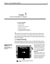
Figure 1.12
Order of Assembly for
the Neutrik Speakon
NL4FC Connector
Figure 1.13
Wiring for the Neutrik
Speakon NL4FC
Connector
Figure 1.14
Stereo Output Wiring