


Chapter 1: Crown Amplifi ers In-Depth 11
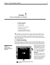
Amplifi er Application Guide
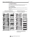
Barrier Block
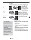
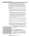
If the amplifi er is set for Stereo (Dual), connect the positive (+) and negative (–) leads
of each loudspeaker to the appropriate Channel 1 and Channel 2 output connectors
as shown in Figure 1.9.
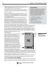
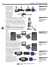
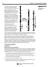
If the amplifi er is set for
Bridge-Mono (if equipped),
connect a mono load across
the positive terminals of each
channel as shown in Figure
1.10. Do NOT use the nega-
tive terminals when the amp
is set for Bridge Output.
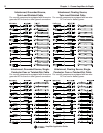
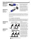
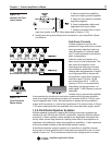
If the amplifi er is set for Parallel-Mono (if
equipped), connect 14-guage or larger
jumper between the Channel 1 and Channel
2 Positive terminals, then connect a mono
load to the Channel 1 positive and negative
terminals as shown in Figure 1.11. Do NOT
use the Channel 2 terminals when the amp
is set for Parallel Output. Caution: Never
short or parallel the output channels of an
amplifi er to itself or to any other amplifi er.
Figure 1.9
Barrier Block Wiring for
Stereo
Figure 1.10
Barrier Block Wiring for
Bridge-Mono
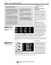
1. To prevent possible short circuits,
wrap or otherwise insulate exposed
loudspeaker cable or cable connectors.
2. Do not use connectors that might
accidentally tie conductors together
when making or breaking the connec-
tion (for example, a standard, 1/4-inch
stereo phone plug).
3. Never use connectors that could
be plugged into AC power sockets.
Accidental AC input will be an electri-
fying experience for your equipment.
But you will fi nd out real quick if your
speakers are any good at 60 Hz!
4. Avoid using connectors with low cur-
rent-carrying capacity, such as XLRs.
5. Do not use connectors that have
any tendency to short.
Output Wiring Tips
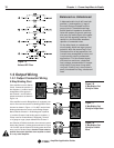
Neutrik
®
Speakon
®
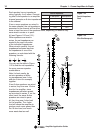
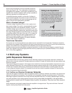
To assemble the Neutrik Speakon NL4FC connector, complete
the following steps:
1. Slide the bushing (E) and chuck (D) onto the end of the cable
as shown in Figure 1.12.
Note: Your NL4FC connector kit should contain both a black
and a white chuck. Use the white chuck for cable with a diam-
eter of 0.25 to 0.5 inch (6.35 to 12.7 mm). Use the black chuck
for cable with a diameter of 0.375 to 0.625 inch (9.525 to
15.875 mm).
2. Strip approximately 3/4-inch (20-mm) of casing from the cable
end. Strip approximately 3/8-inch (8-mm) from the end of each
of the conductors down to bare wire (C).
3a. Insert each wire into the top of appropriate slot of the connec-
tor insert (B) as shown in Figure 1.13. Use a (1.5-mm) allen
wrench or fl at blade screwdriver to tighten the side connecting
screws.
Figure 1.11
Barrier Block Wiring for
Parallel-Mono