


18 Chapter 1: Crown Amplifi ers In-Depth
Amplifi er Application Guide
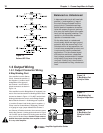
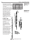
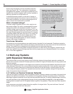
level to drive the speaker, and are connected across the
wires (see Figure 1.26). The combination of transformer
and speaker line presents a much higher impedance to the
amplifi er than would the speaker itself, making it possible to
add many speakers to a single home run.
In distributed speaker systems, as the ratio of voltage to
current become greater, less power is lost on the home run.
This makes it possible to use much smaller gauge wire for
home runs than would otherwise be possible.
What is Constant Voltage?
“Constant-voltage” amplifi ers do not, in fact, supply a con-
stant output voltage. The audio is represented with varying
voltage just as with a low-impedance amplifi er. The term
“constant-voltage” was arrived at for two reasons. First, con-
stant-voltage amplifi ers produce their maximum power when
the output voltage reaches the specifi ed value. For example,
an amplifi er rated at 200 watts, when set to 70V output, will
produce 200 watts when the output voltage reaches 70V.
Second, the output voltage of an amplifi er driving a con-
stant-voltage (distributed) speaker run remains constant
across a wide range of impedances.
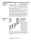
Transformer Saturation
It’s important to know that transformers can easily become “saturated” at low-frequencies. Transformer saturation
occurs when the magnetic fi eld created by the signal content becomes too much for the core of the transformer to
handle. This condition can be dangerous to the amplifi er, and can also cause distortion.
An effective way to prevent step-down transformer saturation is to fi lter the very low-frequency content from the
audio. Your amplifi er may provide high-pass fi lters for this purpose (see your Operation Manual). If not, see Sec-
tion 1.2.2 for fi lter suggestions.
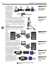
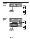
1.4 Multi-way Systems
(with Expansion Modules)
This section shows how multi-way systems can be effectively designed using optional expansion modules that
feature active crossover networks. Example systems are shown for single and multiple amp two-way systems and
three-way systems.
The range of frequencies present in full-range music is wider than most any single speaker component can accu-
rately reproduce. Because of this, most professional speaker systems employ two or more speaker components
to do the job. Crossover networks (or crossovers) are electrical circuits that divide an incoming signal into two
or more separate frequency bands. The separate bands are then routed to speakers designed to reproduce the
range of frequencies they are being fed.
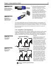
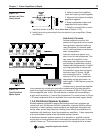
1.4.1 Active vs. Passive Crossover Networks
There are two types of crossovers: active and passive. Passive crossover networks are located in the signal chain
between the amplifi er and speakers. The networks built into speaker cabinets are typically passive. The primary
advantage to passive crossovers is that they use fewer amplifi ed channels. The primary disadvantage is that they
work with amplifi ed or high-voltage signals because of being located after the amplifi er in the signal chain,
causing them to waste much of the power before it gets to the speakers. They also have lower dynamic
range.
Active crossovers are typically located before the amplifi er in the signal chain. They work with lower “line-level”
signals, meaning they waste much less power.
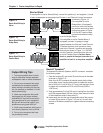
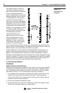
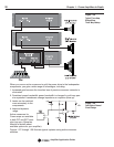
You can use amps without constant-volt-
age settings on distributed speaker sys-
tems if the power output is high enough.
For example, an amplifi er rated for 78
watts output into 8 ohms will directly drive
a 25-volt line. To calculate the necessary
power for driving a specifi c voltage line
use the following formula:
where P equals the necessary power
output,
V equals the voltage of the distributed
speaker system, and R equals the imped-
ance of the amplifi er for the power specifi -
Using Low-Impedance