


Chapter 1: Crown Amplifi ers In-Depth 21
Amplifi er Application Guide
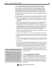
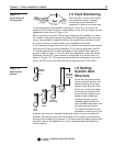
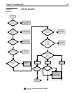
1.5 Fault Monitoring
The Fault (RJ-11) jack, which looks
like a telephone plug, is located
on the back of your amplifi er (if
equipped). It gives you an easy way
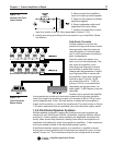
to remotely monitor the amplifi er’s fault status. To set up a circuit that will
cause an LED to light whenever a fault status occurs, you can simply use the
suggested circuit shown in Figure 1.30.
When using this circuit, the LED will glow whenever the amplifi er is in one of
four states: a channel’s heatsink has reached its temperature limit, the trans-
former has reached its temperature limit, the amplifi er has just been turned
on and is in its turn-on-delay mode, or the amplifi er is turned off.
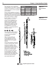
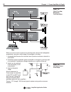
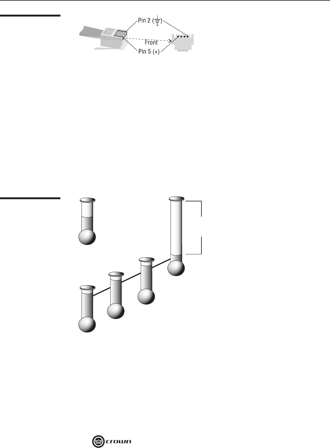
If you choose to design your own circuit to interface this signal to your system,
note that this RJ jack is polarity sensitive. Pin 2 must be grounded, and Pin
5 must be supplied with a positive voltage pull up (positive with respect to
ground). Refer to Figure 1.31 for RJ jack pin assignments. Note: the mating
connector for the RJ-11 jack contains 4 contact pins in a six-slot case, as
shown in Figure 1.31. The maximum signal that can be exposed to the fault
jack is 35 VDC and 10 mA. Best results are obtained with 10 mA LEDs.
1.6 Setting
System Gain
Structure
To get the best performance
from your sound system, you
should carefully set up your
system’s gain structure. Gain
structure is a term that refers
to the way the various levels
are set at each stage of your
sound system. Good gain
structure lets you get your
intended signal out with the
most available headroom, and
the least amount of noise.
This section provides a basic
procedure to use to set up you
system’s gain structure, designed to get you up and running as quickly as
possible. We could go into much more detail on this subject, but that would
be beyond the scope of this manual. If you have questions about system gain
structure, refer to the Appendix for a list of recommended publications for
further reading.
Figure 1.31
RJ Jack Wiring and
Pin Assignments
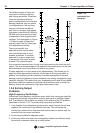
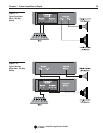
Figure 1.32
Optimal System
Headrom.
Mixer
Input
Mixer
Output
Outboard
Processing
Amplifier
Amplifier
Headroom
Potential
Available
Headroom
Gain