


Chapter 1: Crown Amplifi ers In-Depth 17
Amplifi er Application Guide
4. Never connect the amplifi er’s
input and output grounds together.
5. Never tie the outputs of multiple
amplifi ers together.
6. Keep loudspeaker cables well
separated from input cables.
7. Install a low-pass fi lter on each
input line (similar to the RF fi lters described in Section 1.2.2).
8. Install input wiring according to the instructions in your amplifi er’s Opera-
tion Manual.
Sub-Sonic Currents
Another problem to avoid is the
presence of large sub-sonic currents
when primarily inductive loads are
used. Examples of inductive loads
are 70-volt transformers and electro-
static loudspeakers.
Inductive loads can appear as a
short circuit at low frequencies. This
can cause the amplifi er to pro-
duce large low-frequency currents
and activate its protection circuitry.
Always take the precaution of install-
ing a high-pass fi lter in series with
the amplifi er’s input when inductive
loads are used. A 3-pole, 18-dB-
per-octave fi lter with a –3 dB fre-
quency of 50 Hz is recommended
(depending on the application, an
even higher –3 dB frequency may be
desirable).
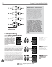
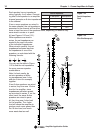
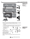
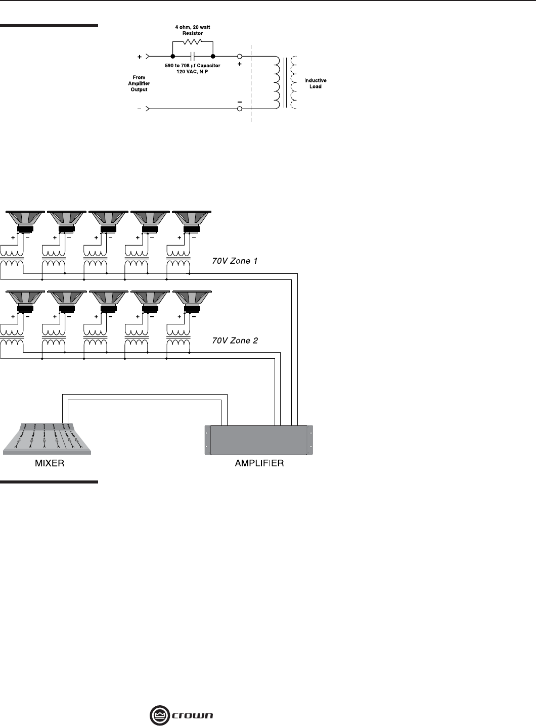
Another way to prevent the amplifi er
from prematurely activating its protection systems and to protect inductive
loads from large low-frequency currents is to connect a 590 to 708 µF nono-
larized capacitor and 4-ohm, 20-watt resistor in series with the amplifi er’s
output and the positive (+) lead of the transformer. The circuit shown in Figure
1.25 uses components that are available from most electronic supply stores.
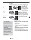
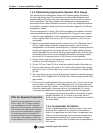
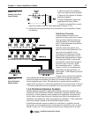
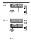
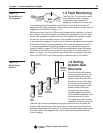
1.3.6 Distributed Speaker Systems
Multiple-speaker systems for paging and background music systems are
common in such facilities as schools, restaurants, industrial facilities offi ces
and retail. In these systems, many speakers are distributed throughout the
facility, often across long distances, making them diffi cult and expensive to
implement with traditional, direct low-impedance amplifi ers. A less expensive
and more reliable method is the distributed speaker system.
A distributed speaker system consists of an amplifi er or amplifi er channel
driving one or more speakers with transformers connected to a pair of wires
called a “home run.” The transformers step the line voltage down to a lower
Figure 1.25
Inductive Load (Trans-
former) Network
Figure 1.26
Typical Distributed
Speaker System