


11
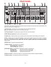
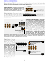
11. Component Video outputs - Switched output connections for your component video monitor.
Red RCA jack - typically connect to the red input on a component video monitor
Green RCA jack - typically connect to the green input on a component video monitor
Blue RCA jack - typically connect to the blue input on a component video monitor
12. Component Video inputs - Switched input connections for three component video devices.
Red RCA jack - typically connect to the red output of a component video source
Green RCA jack - typically connect to the green output of a component video source
Blue RCA jack - typically connect to the blue output of a component video source
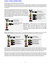
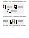
13. Line inputs - Connections from your audio/video sources.
Red RCA jacks - right analog audio
White RCA jacks - left analog audio
Yellow RCA jacks - composite video
4 pin din jacks - S-video
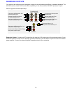
14. Line level outputs - Fixed level outputs to an audio or video recorder.
15. Zone 2 outputs - Variable level outputs to your video monitors and external amplifiers.
16. Zone 1 outputs - Video outputs to your video monitors.
17. Optical Digital inputs - Optical digital inputs are used to connect digital audio signals from your source to the
receiver. The incoming signal may be PCM, Dolby Digital or DTS.
18. Optical Digital output - Zone 1 optical output to carry digital information from the selected digital input of the
receiver out to digital recorders, personal computers, etc.
19. Coax Digital inputs - Coax digital inputs are used to connect digital audio signals from your source to the
receiver. The incoming signal may be PCM, Dolby Digital (AC-3) or DTS.
20. Coax Digital output - Independent Zone 1, and Zone 2, coax outputs to carry digital information from the
selected digital input of the receiver out to digital recorders, personal computers, etc.
21. Expansion (optional) - For future format and interface applications.
The serial number of your unit is located above the expansion port.