


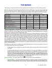
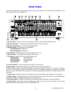
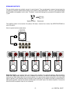

REAR PANEL
The receiver’s back panel is organized into groups of inputs and outputs for audio and video as shown below. See
back of this manual for an enlarged view.
1. AC fuse holder
- Holds the AC Line fuse. Replace only with 12 Amp / 250 Volt Slow Blow fuse.
2. AC input receptacle
- For attaching the supplied AC power cord to the receiver.
3. RS-232 input (optional)
-
For future interface applications.
4. Speaker outputs
- Connections for your speakers.
Red binding posts
- speakers (+)
Black binding posts
- speakers (-)
5. Serial number
-
B&K Components, Ltd. serial number of your unit.
6. Antenna inputs
-
Connections for the AM and FM antennas.
7. Line inputs
- connections from your audio/video sources.
Red RCA jacks
- right analog audio
White RCA jacks
- left analog audio
Yellow RCA jacks
- composite video
4 pin din jacks
- S-video
8. Line level outputs
- Fixed level outputs to an audio or video recorder.
9. Zone outputs -
Variable level outputs to your video monitors and external amplifiers.
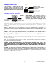
10. IR in
- Accepts input from external IR receptors. Connect an IR repeater (“home run”) to IR IN for controlling
the receiver. This method of control is useful when the front IR receptor is blocked (for example, by a cabinet
door) or to control the receiver from another room. This input is typically used in place of an emitter attached to the
front panel.
11. Control outs
- Outputs that allow you to remotely control external devices. (See “Making The Connection“).
12. Digital outputs
- One optical and one 3.5 mm coaxial that carry digital information from the selected digital
input of the receiver out to digital recorders, personal computers, etc.
13. Surround outputs
- Variable level outputs for driving external power amplifiers or powered speakers.
14. Digital inputs
- Inputs used to connect a digital audio signal from your source to the receiver. The incoming
signal may be PCM, Dolby Digital (AC-3) or DTS (AVR202 only).
8
p/n 12699 Rev. 9812C