


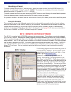


6. Once you have configured the settings for your system, save the BKcSuite file. Goto File->Save
settings To File. Both the system settings and presets for zone A and zone B will be saved together in
one file (.bkd extension). Once the settings have been saved to file, you are ready to establish a live
connection to the preamplifier.
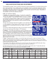
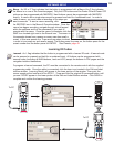
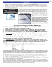
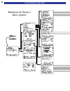
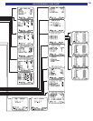
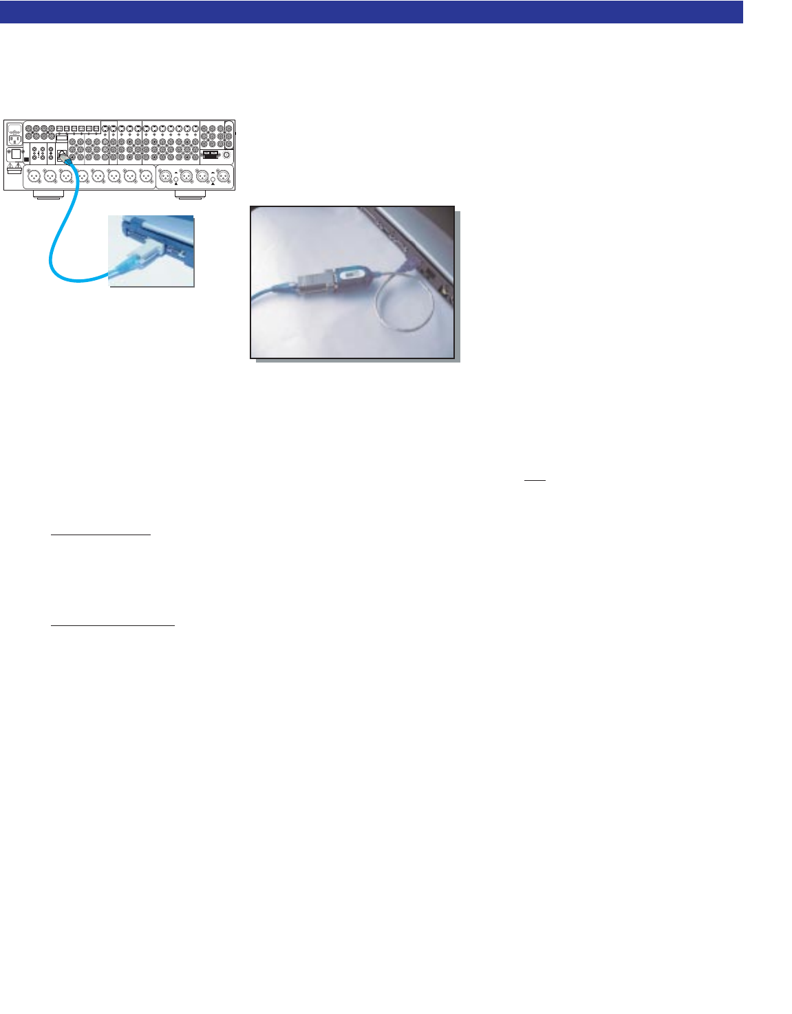
7. Connect a straight through CAT5 network cable between the RJ-45
jack and the serial port of the PC (pictured at left). If the PC does not
have a DB-9 type serial port, a serial to USB adapter can be used. To
establish a live connection, close and
re-open BKcSuite. BKcSuite will search
all com ports for a connected device.
While a live connection is established,
BKcSuite will operate the same way as
when in virtual mode, however any
changes made in BKcSuite will immedi-
ately update inside the unit itself. To
upload a saved file, goto File->Open
and open the saved system setting file
while a live connection is established.
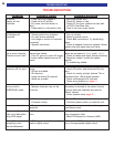
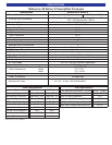
Troubleshooting Guide For BKcSuite
1. PC requirements - 128MB RAM, Pentium grade or better processor, Windows 98SE operating system or
greater. (Exception- BKcSuite not supported on Windows NT) ***
2. Make sure the CT/CK/SR product is connected to the PC’s serial port. (DB-9, nine pin or USB)
3. Be sure to select “Local Com” in the BKcSuite software, as “Network” is not
currently supported.
4. If the unit will not communicate through RS-232, perform a factory reset. (See Factory Reset Section)
5. Know how to properly set the COM port protocol in your version of Windows:
Window 9x/Me
- Go to your system’s “Control Panel.” Double click the icon labeled “System.” Click
the Device Manager button. Scroll down until the section labeled “Ports.” Click the small “+” located next to
“Ports” to expand the tree and view the installed communication ports. Double click the COM port that corre-
sponds to the port on the PC that the CT/CK/SR product will be physically connected to. Locate the tab in
the Window labeled “Port Settings,” click it and go to section 6 below.
W
indows 2000/XP - Go to your system’s “Control Panel.” Click the icon labeled “System.” In the
Hardware tab, click the Device Manager button. Double click on the icon labeled “Ports” to expand the tree
and view the installed communication ports. Double click the COM port corresponding to the port the
CT/CK/SR product is physically connected to and go to section 6 below.
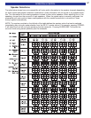
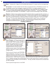
6. Set the proper communication properties. The parameters for Port Settings should be entered as
follows: Bits per second - 9600
Data Bits - 8
Parity - None
Stop Bits - 1
Flow Control - None
In the advanced section of the Communication properties window is the “FIFO Buffer” configuration. Most
modern laptops have the ability to take full advantage of these buffers, so it is recommended to enable them
and drag their slider to the “max” setting. Once you have finished making the selections, click “OK” to all
windows and prompt to return to the Control Panel. At that point you can close the Control Panel.
7. Disable any and all power management services including any Uninterrupted Power Supplies (UPS).
8. Disable any handheld computer / PDA syncing software and services.
9. Disable any other RS-232 / Serial protocol programs that may be using a COM port. i.e CK1.2 Keypad
Editor, SR10.1 Remote Editor or serial controller.
10. In case you encounter an “Out of Memory” or “Out of Resources” error, be sure your PC meets the
minimum requirements outlined in the BKcSuite section of this manual. Close all unnecessary programs that
may be running. It is recommended to let Windows manage your virtual memory, however, if you manually
set the virtual memory size, set it at least to 1.5 times your actual RAM size.
55
SOFTWARE SETUP
ACLINE
www.bkcomp.com
SURROUND
LEFT
FRONT
LEFT
CENTER
FRONT
RIGHT
SURROUND
RIGHT
FUSE
CAUTION: FORCONTINUED
PROTECTION AGAINSTRISK
OF FIREREPLACE ONLYWITH
SAME TYPEANDVALUEFUSE
Audio/VideoSystems Hand-MadeintheU.S.A.
FRONTSURRND
SUB CENTER
+
SERIAL#
IN 1
IN 2
IN 3
V1
V2
TVDVDCDSATTAPETAPE
V1
ZB/V2
AUDIO
DVD
INPUT
A/V SOURCE OUTPUTS A/VSOURCE INPUTS COMPONENT VIDEO
AM FM
ANTENNA
ZONE B
OUTPUTS
ZONE BFRONTSURRND SBACK
CENTERSUB
SURROUND OUTPUTS
OPTICAL S/PDIF DIGITALCOAX S/PDIF DIGITAL
OUT SAT CD DVD V2 V1
V1V2TVZA OUT
ZB OUT SAT CD DVD
CONTROL OUT IRINPUT
ZONE A
IEEE
1394
12VDC
50mA
21
34
CAUTION
RISKOF ELECTRIC
SHOCKDO NOT OPEN
RISKOF ELECTRIC
SHOCK
DONOT OPEN
BK
&
SB
IMPLYETTER!
IR INPUT
ZONE B
EXPANSION
OUTPUT
BALANCEDSURROUND OUTPUTS
SUBWOOFER
BALANCEDLINE INPUTS
RIGHT
LEFT
RIGHT
LEFT
XLR
(BALANCED)
RCA
(UNBALANCED)
DVD
XLR
(BALANCED)
RCA
(UNBALANCED)
CD
SURROUNDBACK
RIGHT
SURROUNDBACK
LEFT
RS-232
PORT
ZONE A
USB to Serial adapter
CAT5 Network Cable