


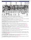

18
HARDWARE CONNECTIONS
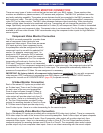
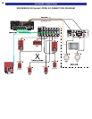
PASS THROUGH / RECORD LOOP CONNECTIONS
The B& K preamplifier has a few options for record/pass through outputs. There is a Zone A optical digital
output, a Zone A coaxial digital output and a Zone B coaxial digital output. The B &K preamplifier provides
three analog audio, composite & S-video outputs. These outputs are labeled TAPE, V1 and Z2/V2 in the Line
Outputs section of the back panel.
Optical Digital Output - The optical digital output will output the digital signal of the source selected in the
main theater zone (Zone A). Coaxial digital inputs are converted to optical. You need only connect one or the
other. Analog inputs are not converted to digital output. If you wish to record both analog and digital sources
you must connect both analog and digital inputs to your recorder.
Zone A and Zone B Coaxial Digital Outputs - The Zone A and Zone B coaxial digital outputs will output the
digital signal of the source selected in the corresponding zone. Optical digital inputs are converted to coaxial.
You need only connect one or the other. Analog inputs are not converted to coaxial digital output. If you wish
to record both analog and digital sources you must connect both analog and digital to your recorder.
Tape Out - The analog Tape output is a pass through / record loop output for the source that is selected in
the main theater zone. To prevent possible speaker damaging feedback, tape out will not output the TAPE
source input. Digital audio is not converted to analog audio on the Tape output. You must connect analog
audio to the A/V inputs if you want to make analog recordings from the input device. Only LtRt mode will
downmix a digital bitstream into left and right analog. Video is not transcoded on the Tape output. If you have
a composite recorder you must connect composite from each A/V source you wish to record. If you have a S-
video recorder you must connect S-video from each A/V source you wish to record.
V1 Out - The V1 output can be configured as an output for a second recording device in Zone A or as a Zone
A line output to connect a second video monitor and/or audio amplifier. As a record output, V1 will output the
analog audio and video from the selected input in Zone A except when V1 is selected. This prevents
feedback through the recording device which could damage your speakers. As a line output V1 will output the
analog audio and video from whatever input is selected in Zone A. LtRt mode will downmix a digital bitstream
to left and right. Record/Line settings also apply to the Zone A optical and coaxial digital outputs. Similar to
the Tape output, digital audio is not converted to analog on the V1 output. Video is also not transcoded on the
V1 output. To configure the V1 output see page 33.
ZB / V2 Out - The V2 output can be configured as an output for a second recording device in Zone B or as a
Zone B line output to connect a second video monitor and/or audio amplifier. As a record output, V2 will
output the analog audio and video from the selected input in Zone B except when V2 is selected. This
prevents feedback through the recording device which could damage your speakers. As a line output V2 will
output the analog audio and video from whatever input is selected in Zone B. Record/Line settings also apply
to the Zone B optical and coaxial digital outputs. As with the Tape output, digital audio is not converted to
analog on the V2 output. Nor is video transcoded on the V2 output. To configure the V2 output, see page 38.
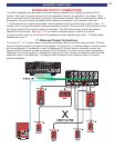
CONTROL OUTPUT CONNECTION
The B& K surround preamplifier is supplied with four control outputs. These control outputs can be used for a
variety of applications that require a 12 volt control or an IR output (pass through). The control outputs use a
1/8” (3.5mm) mono mini plug. Each output is 10-12VDC @ 50 mA. Control output 1 is strictly a +12VDC
control trigger. Control outputs 2-4 can be set up as either +12VDC controls or as an IR pass through. To
configure the control outputs, see the control setup section on page 34.
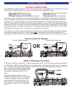
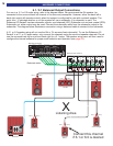
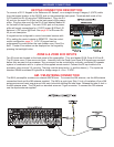
IR Emitter Connection
To connect an IR emitter to the control output, one end should be
terminated into a 3.5mm mono mini plug, tip (+), sleeve (-). The IR
output will pass through IR signals received by the surround pream-
plifier. Only industry standard 38kHz IR may be used with the IR
outputs. Additional resistance may be required in series with the IR
emitter, check the current rating of the emitter you are using.
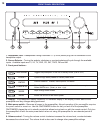
L
Audio/VideoSystemsHand-Madein theU.S.A.
FRONTSURRND
SUB CENTER
+
IN 1 IN 2 IN 3V1V2TVDVDCDSATTAPETAPE
V1
ZB/V2
DVD
INPUT
A/V SOURCE OUTPUTS A/VSOURCE INPUTS COMPONENT VIDEO
AM FM
ANTENNA
ZONE A ZONE B
OUTPUTS
ZONE BFRONTSURRND S BACK
CENTERSUB
SURROUND OUTPUTS
OPTICAL S/PDIF DIGITALCOAX S/PDIF DIGITAL
OUT SAT CD DVD V2 V1
V1V2TVZA OUT
ZB OUT SAT CD DVD
CONTROL OUT IR INPUT
ZONE A
IEEE
1394
12VDC
50 mA
21
34
OUTPUT
IR INPUT
ZONE B
AUDIO
RS-232
PORT
PLAY 8:33
PLAY 8:33