


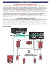
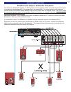


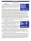

KEYPAD CONNECTION DESCRIPTION
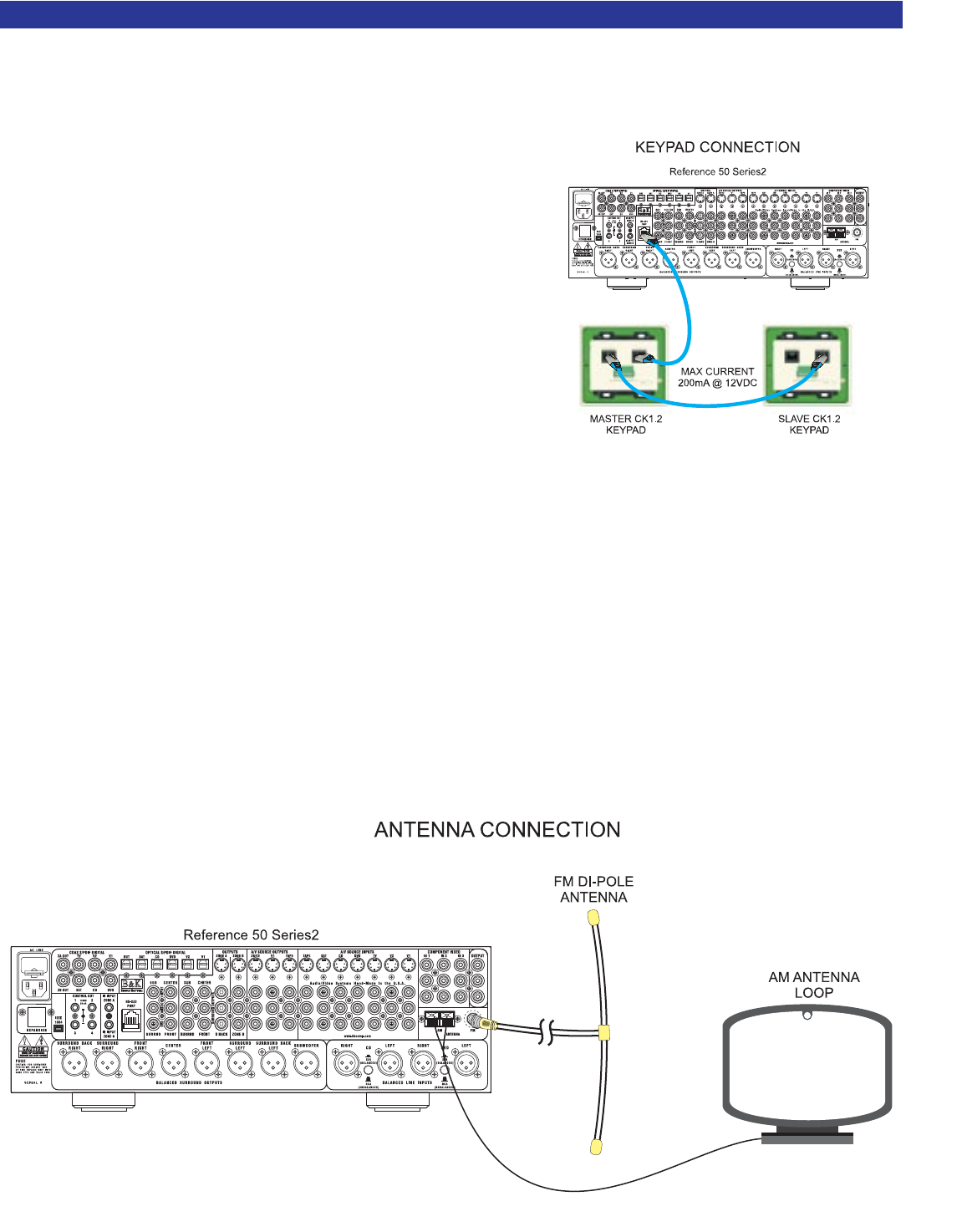
To connect a CK1.2 Keypad to the Reference 50 Series2, run a straight through Category 5 (CAT5) cable
from the keypad location to the RS-232 jack on the preamplifier back panel. Terminate both ends of the
CAT5 cable into RJ-45 using the T568B standard. Plug one RJ-
45 end into the main RJ-45 jack on the back panel of the pream-
plifier. Plug the other end into the RJ-45 jack labeled Master IN
on the back of the keypad. The main RJ-45 jack on the pream-
plifier will supply connections for +12VDC power @ 200mA, IR
data and +12V control @ 50mA. See page 36 for the main RJ-
45 pin out description.
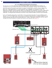
A keypad can be configured to control connected sources with
IR by setting the control outputs to REMOTE. See the control
output configuration page 34. A CK1.2 keypad can be
programmed to control either the main theater zone, Zone B or
both. Theater Zone status can be displayed on the keypad by
pressing the backlight button.
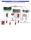
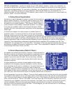
ZONE A & ZONE B IR INPUTS
Two IR inputs are located on the back panel of the preamplifier. They are labeled IR IN, Zone A & Zone B.
The IR inputs use a 3.5mm mono mini jack. Internally, both the Zone A and Zone B IR signals are summed
before they are sent to the processor. Your processor can be controlled by a directly connected IR repeater
system in combination with or in place of the supplied remote control. Connect the IR input cable to the
processor using a mono 3.5 mm plug. The plug must be wired as tip (+) and the sleeve (-). The inputs are
standard 38kHz modulated IR type with a voltage range of +5 to +12 VDC.
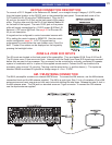
AM / FM ANTENNA CONNECTION
The B& K preamplifier contains one internal AM/FM tuner. To connect the AM antenna, use the AM antenna
connection block and the AM antenna supplied. The AM is a push type. Strip ¼ inch of insulation off your AM
antenna wires and insert one wire end into each hole while holding the tabs down. Release the tabs to lock in
the AM antenna wires. The FM jack is a standard screw on F-type connector. To connect the FM antenna
use the dipole antenna supplied.
21
HARDWARE CONNECTIONS