


MIDI FOOT CONTROLLER FCB1010
5
1. INTRODUCTION
Congratulations! With the BEHRINGER MIDI FOOT CONTROLLER
FCB1010 you purchased an ultra-flexible controller unit for a
wide range of applications, whether you are a guitarist, keyboard
player or studio engineer: 10 BANKS with 10 PRESETS each and
two fully user-programmable expression pedals will give you
enough flexibility to manage your MIDI equipment. Guitar players
will particularly appreciate the option of selecting channels using
two analog SWITCHES, as they allow you to fully control both
amplifier and effects from one switching center. And with its
ultra-rugged enclosure and built-in power supply the FCB1010
is absolutely ready for the road, too. The easy-to-use
programming interface gives you fun instead of frustration, and
invites you to fully exploit the capabilities of your MIDI equipment.
+ The following users manual is intended to
familiarize you with the units control elements,
so that you can master all the functions. After having
thoroughly read the users manual, store it at a safe
place for future reference.
1.1 Before you get started
1.1.1 Shipment
The FCB1010 was carefully packed at the factory to assure
secure transport. Should the condition of the cardboard box
suggest that damage may have taken place, please inspect the
unit immediately and look for physical indications of damage.
+ Damaged units should NEVER be sent directly to us.
Please inform the dealer from whom you acquired
the unit immediately as well as the transportation
company from which you took delivery of the unit.
Otherwise, all claims for replacement/repair may
be rendered invalid.
1.1.2 Initial operation
Please make sure the unit is provided with sufficient ventilation,
and never place the FCB1010 on top of an amplifier or in the
vicinity of a heater to avoid the risk of overheating.
+ Before plugging the unit into a power socket, please
make sure you have selected the correct voltage:
The fuse compartment near the power plug socket contains
three triangular markings. Two of these triangles are opposite
one another. The voltage indicated adjacent to these markings is
the voltage to which your unit has been set up, and can be
altered by rotating the fuse compartment by 180°. ATTENTION:
This does not apply to export models that were for
example manufactured only for use with 120 V!
+ If you alter the units voltage, you must change the
fuse accordingly. The correct value of the fuse
needed can be found in the chapter
SPECIFICATIONS.
+ Faulty fuses must be replaced with fuses of
appropriate rating without exception! The correct
value of the fuses needed can be found in the
chapter SPECIFICATIONS.
Power is delivered via the cable enclosed with the unit. All
requiered safety precautions have been adhered to.
+ Please make sure that the unit is grounded at all
times. For your own protection, you should never
tamper with the grounding of the cable or the unit
itself.
1.1.3 Warranty
Please take a few minutes and send us the completely filled
out warranty card within 14 days of the date of purchase. You
may also register online at www.behringer.com. The serial number
needed for the registration is located at the top of the unit. Failure
to register your product may void future warranty claims.
1.2 The users manual
The users manual is designed to give you both an overview of
the control elements, as well as detailed information on how to
use them. In order to help you understand the links between the
controls, we have arranged them in groups according to their
function. If you need to know more about specific issues, please
visit our website at www.behringer.com, where youll find
additional information on mixing consoles, effects units and
dynamic processors.
1.3 Control elements
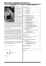
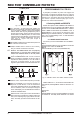
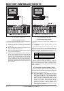
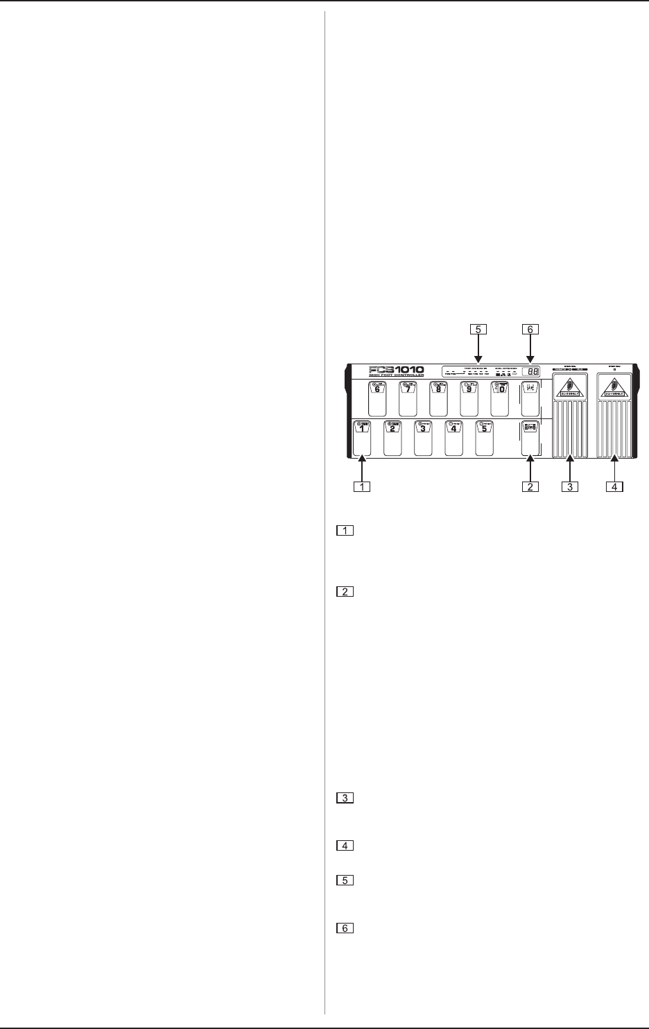
1.3.1 Front panel
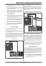
Fig. 1.1: Front panel control elements
FOOTSWITCHES 1 through 10/0. These keys are used
for changing the presets, programming, entering values in
programming mode and activating the DIRECT SELECT
function (10/0 only).
UP/DOWN keys. These keys are used to navigate through
different banks and programming layers. When in
programming mode, use the UP key for ENTER (confirm)
and the DOWN key for ESCAPE (cancel).
+ When DIRECT SELECT mode is activated (see
chapter 2 PROGRAMMING THE FCB1010), the UP/
DOWN switches are no longer needed for BANK
selection and are free to perform a special function:
in the GLOBAL CONFIGURATION menu you can
program them to control the SWITCH RELAYS (UP:
SWITCH 1 RELAY, DOWN: SWITCH 2 RELAY). In this
case, you can toggle between the preprogrammed
SWITCH settings, each time you step on these
switches.
EXPRESSION PEDAL A. Allows you to change controller
values continuously. In programming mode, the pedal is
used for data entry.
EXPRESSION PEDAL B. Allows you to change controller
values continuously.
STATUS LEDs. The yellow LEDs display the current status
of the PRESET programming or GLOBAL CONFIGURATION
functions.
LED display. Informs you about the currently selected
BANK/PRESET number. In programming mode, it displays
any value changes.
1. INTRODUCTION