


7
2
Using either the UP or DOWN button [ ] the desired receiving frequency
or channel number can be set. Tapping the button steps the frequency or
channel number one at a time while pressing and holding the button moves
through the frequencies or channel numbers rapidly. There are 188 different
frequencies or channel numbers to choose from. Once the desired frequency
or channel has been determined be certain to set both the transmitter and the
receiver to match.
s
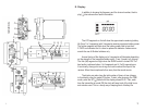
USING THE 1201 TRANSMITTER CONTROLS AND DISPLAY
A. Power:
B. Audio:
C. MIC:
The POWER ON/OFF switch [ ] turns the 1201BT On and Off.
l
Prior to turning the 1201BT ON it is best to set the AUDIO switch [ ] to
ST.BY. When ready to transmit, switch to ON. The ST.BY position acts as a
“mute” that maintains the RF signal but turns off the audio.
n
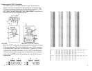
This 4-pin Hirose connector [ ] is the microphone input. Azden produces a
number of lapel, head-worn and neck-worn microphones that are specically
suited for the 1201BT. In addition, other externally powered (5VDC) electret
condenser microphones can be used when they are properly wired with the
correct Hirose connector) pin #1 is for audio +, pin #2 is not used, pin #3 is for
bias voltage and pin #4 is ground). If you are using the 1201BT as a wireless
instrument transmitter the connections are somewhat different (pin #1 is not
used, pin #2 is audio +, pin #3 is for bias voltage and pin #4 is ground).
o
D. Input Level Adjustment:
E. Belt-Clip:
This screwdriver adjustment [ ] controls the level of the microphone.
Counterclockwise rotation reduces the input gain while clockwise rotation
increases the input gain.
*
The metal belt-clip [ ] provides a convenient method of attaching the trans-
mitter to the user.
j
RECEIVER SETUP/USE - 1201URX/AB or 1201URX/VM (continued)
Using either the UP or DOWN button [ ] the desired receiving frequency
or channel number can be set. Tapping the button steps the frequency or
channel number one at a time while pressing and holding the button moves
through the frequencies or channel numbers rapidly. There are 188 different
frequencies or channel numbers to choose from. Once the desired frequency
or channel has been determined be certain to set both the transmitter and the
receiver to match.
s
D. Power:
The POWER ON/OFF switch [ ] turns the 1201BT On and Off. To conserve
battery life, it is best to turn the receiver ON only when it is actually being
used.
p
E. Output:
Select either LINE or MIC [ ] depending on which input is being used on the
camera
q
F. Monitor:
This control [ ] adjusts the output level (MIN to MAX) at the earphone moni-
tor jack [ ]. This is a 3.5mm mono jack.
k
n
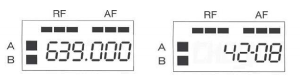
G. LCD Display:
This display [ ] shows several pieces of information. As discussed previ-
ously, the frequency or channel number is shown. Additionally, as the diver-
sity receiver chooses which antenna is receiving the best signal, The ‘A’ or ‘B’
segment of the LCD display will illuminate.
o