


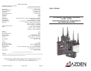
RECEIVER SETUP (1201URX/AB and 1201URX/VM)
The 1201URX/AB is a specially developed model that integrates the Anton
Bauer “Gold Mount” to power the receiver. The 1201URX/VM is a specially
developed model that integrates the IDX battery-mount to power the receiver.
All of the functions and controls of the two models are the same except for
the method of powering the receiver. The 1201URX/AB attaches between
the camera and Anton Bauer pack using the “Gold Mount” system while the
1201URX/VM attaches between the camera and the IDX “V-mount” battery
pack.
A. Attaching antennas:
To attach the high-gain antennas to the receiver, t the BNC connector on the
antenna on the receiver [ ], press down and rotate clockwise. To remove,
rotate the antenna’s BNC connector counterclockwise and pull up.
j
B. Connecting the Output cable:
It is necessary to connect the output of the receiver [ ] to the camera’s
“MIC” or “LINE” input by means of a properly wired cable (not supplied). The
connector on the receiver is wired with pin #1 as Ground, pin #2 as Posi-
tive (+) and pin #3 as Negative (-). Set the OUTPUT Line/Mic switch on the
receiver [ ] to the appropriate position, matching the input on the camera
that is used.
l
q
C. Setting the Receiving Frequency:
Before the receiver can be used, it and the associated transmitter have to be
set to the same frequency. This can be accomplished on the receiver by rst
setting the LCD display to one of two views - “Frequency” or “Channel”. To
do this, after applying battery power, st turn the receiver to the ON position
[ ]. Next, using the tip of a ballpoint pen, an unbent paperclip or something
similar, press the MODE button [ ] repeatedly until one of the two screens
on the next page appears.
p
r
F. Antennas:
The antennas [ ] should be kept clear of metal objects.
k
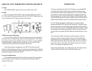
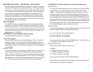
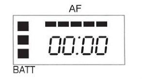
G. Display:
In addition to showing the frequency and channel number, the display [ ]
also shows other useful information.
p
The LCD segments on the left show the approximate remaining bat-
tery life (from 1 to 3 segments) with 3 segments meaning maximum battery
power. The bottom segment will blink when the battery power falls to less the
2.2VDC and indicates that it is time to replace the batteries. Azden recom-
mends the use of Alkaline batteries only.
Across the top of the display up to 5 segments will illuminate depending
on the strength of the transmitted audio signal - From 2 (weak) to 5 (strong).
The rst (left) segment will light when the STBY switch is turned ON. The best
audio is achieved when 4 to 5 segments are lit. If all 5 segments are lit con-
tinually, the signal is too strong and could overload the input of the receiver.
Either move the microphone further away from the sound source or reduce
the microphone input gain [ * ].
The display can also show the total number of hours of use (change
to this display using the mode [ ] button. To start, after choosing the TIME
mode, press the UP [ ] Button until the display shows 00:00. Then, each
time the transmitter is turned ON the clock will keep track of the total hours
and minutes used. This is a handy way of keeping track of battery life.
q
s
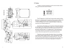
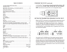
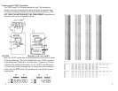
POWERING THE 1201XT TRANSMITTER
The 1201XT uses two “AA” Alkaline batteries for power. The batteries are
placed in the compartment by removing the battery compartment door and
placing the batteries in the compartment as shown
8
1