


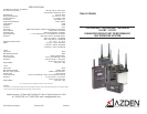
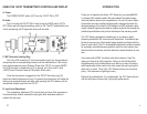
INTRODUCTION
Thank you for selecting the Azden 1201 Series for your portable/ENG
on-camera UHF wireless needs. We are condent that these compo-
nents will perform beyond your expectations. For over 50 years, Azden
Corporation has been creating technologically advanced products. By
taking advantage of the latest in CAD design and SMT production tech-
niques, Azden’s engineers are able to produce products that exceed the
published specications and perform well beyond the warranty period.
The 1201 Series represents a breakthrough in on-camera, digital
frequency-selectable UHF receivers and transmitters. Its enhanced per-
formance assures you of the highest image rejection combined with the
nest in audio clarity. The PLL-synthesized mixer/local oscillator provides
for extremely accurate frequency selection while the twin-antenna true
diversity front-end reduces multi path distortion caused dropouts to near
zero.
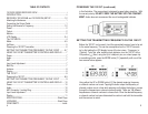
In the real world of ENG, the ability to be able to select a “clear” fre-
quency on the spot is vitally important. Going out into the eld with a
single-frequency unit invites disaster since there is no way of knowing
what frequencies will be used by the other crews that are covering the
same story or event. Think of the 1201 Series units as your insurance
policy - Your assurance of getting the story.
Designed by professionals - For professionals, the 1201 Series will pro-
vide you with years of worry-free, high-quality performance.
ii
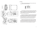
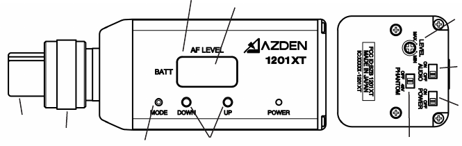
USING THE 1201XT TRANSMITTER’S CONTROLS AND DISPLAY
A. Power
The POWER ON/OFF switch [ ] Turns the 1201XT ON or OFF.
B. Audio
Prior to turning the 1201XT ON it is best to set the AUDIO switch [ ] To
OFF. When ready to begin transmitting, switch to ON. The OFF position acts as a
“mute” maintaining the RF signal but turning off the audio.
q
r
k
l
n
o
p
q
r
s
m
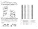
C. MIC Connector/Locking Ring
This 3-pin XLR connector [ ] Is the microphone input. Any low impedance
microphone with a corresponding connector can be attached here. If the microp
hone requires external power (Phantom Power) the 1201XT can supply 48VDC.
The XLR connector is wired with pin #1 as ground, pin # 2 as audio + (and
+48VDC when Phantom Power is ON) and pin #3 as audio -.
Once the microphone is plugged into the 1201XT the locking ring [ ]
should be rotated clockwise until snug. To remove the microphone, rst rotate the
locking ring counterclockwise and then, while pressing the XLR release, pull the
microphone straight away from the 1201XT.
D. Input Level Adjustment
This screwdriver adjustment [ ] controls the input level of the microphone.
Counterclockwise rotation reduces the input gain while clockwise rotation in-
creases the input gain.
l
m
p
10
j