


ASUS P/I-P55T2P4 User's Manual24
III. INSTALLATION
(Connectors)
III. INSTALLATION
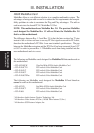
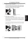
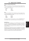
14. CPU Cooling Fan Connector (FAN)
This connector supports a CPU cooling fan of 500mAMP (6WATT) or less.
Orientate the fan so that the heat sink fins allow airflow to go across the on-
board heat sink(s) instead of the expansion slots. Depending on the fan manu-
facturer, the wiring and plug may be different. The red wire should be posi-
tive, while the black should be ground. Connect the fan's plug to the board
taking into consideration the polarity of the this connector.
WARNING: The CPU and/or motherboard will overheat if there is no airflow
across the CPU and onboard heatsinks. Damage may occur to the mother-
board and/or the CPU fan if these pins are incorrectly used. These are not
jumpers, do not place jumper caps over these pins.
Air Flow
Air Flow
CPU Fan Power
FAN
+12V
GND
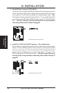
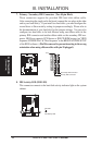
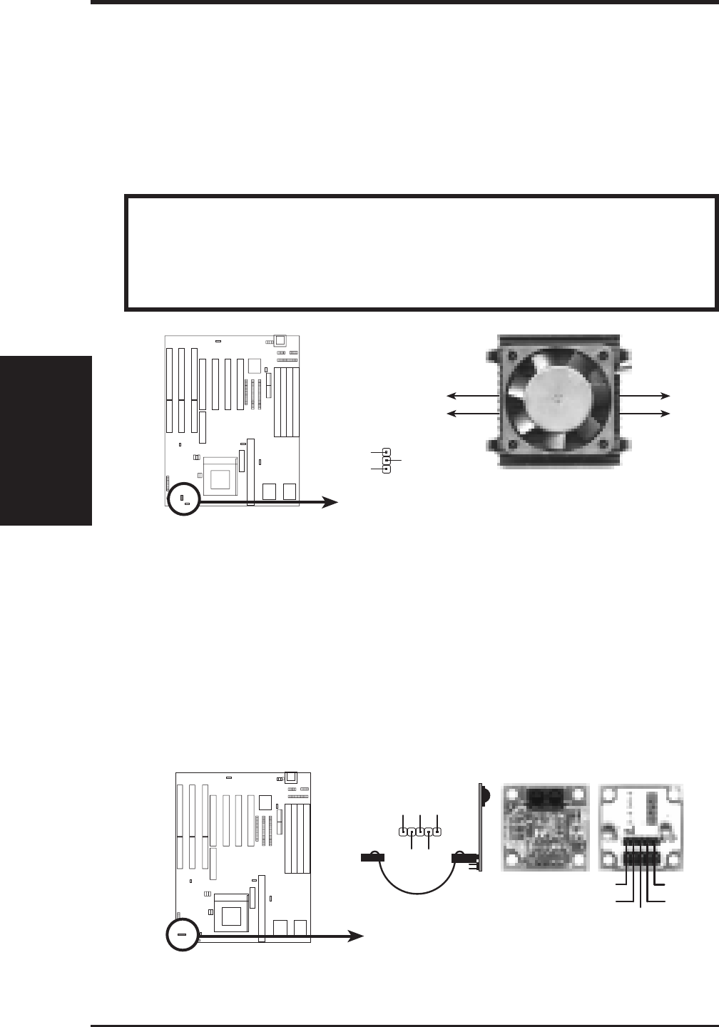
15. IrDA-Compliant Infrared Module Connector (IR)
This connector supports the optional wireless transmitting and
receiving infrared module. This module mounts to a small opening on system
cases that support this feature. You must also configure the setting through
BIOS setup on page 36 "UART2 Use Infrared" to select whether UART2 is
directed for use with COM2 or IrDA. Use the five pins as shown on the Back
View and connect a ribbon cable from the module to the motherboard accord-
ing to the pin definitions.
Infrared Module Connector
Front View
+5V
IRTX
IRRX
NC
GND
Back View
IRRX
+5V
IRTX
NC
GND