


54 ASUS P/I-P55T2P4 User's Manual
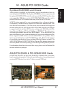
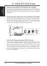
Setting Up the ASUS PCI-SC200 & PCI-SC860
There are two jumper settings you may need to make on the ASUS PCI-SC200 to set
it up. One setting assigns the PCI INT interrupt, the other sets the card’s termination.
The ASUS PCI-SC860 has no jumper settings but you should read the “Terminator
Requirements.”
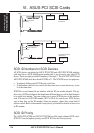
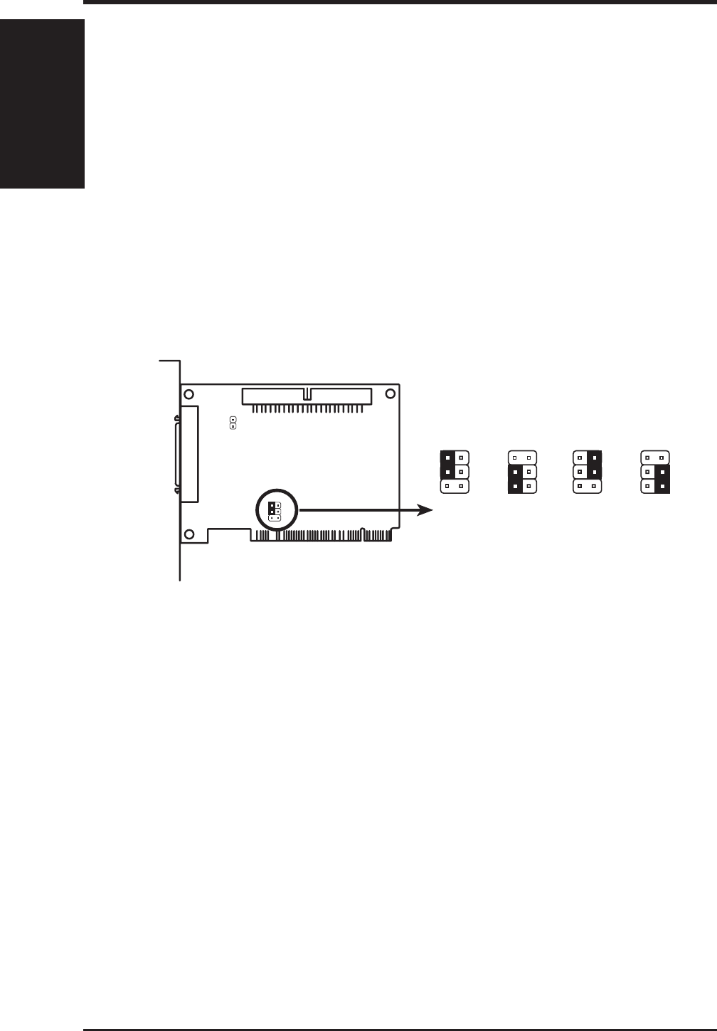
Setting the INT Assignment for the ASUS PCI-SC200
You must use PCI INT A setting in order to properly assign the ASUS PCI-SC200's
interrupt. On the ASUS PCI-SC200, you assign the INT by setting jumper JP1 or
JP2. The default setting for the card already is INT A, so you do not need to change
the setting to use the ASUS PCI-SC200 with this motherboard.
JP
1
JP
2
INT A (Def)
1
2
3
Interrupt Settings (A, B, C, or D)
JP
1
JP
2
INT B
1
2
3
JP
1
JP
2
INT C
1
2
3
JP
1
JP
2
INT D
1
2
3
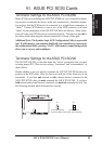
Terminator Requirements for SCSI Devices
SCSI devices are connected together in a “chain” by cables. Internal devices con-
nect to the ASUS PCI-SC200 or ASUS PCI-SC860 with a fifty-pin flat ribbon cable.
External devices connect to the external port with a SCSI-2 cable. If there are more
than one internal or external devices, additional devices are connected with cables
to form a “daisy chain.” Terminating the devices on the ends of the SCSI Bus “chain”
is necessary for SCSI devices to work properly. Termination of the devices between
the ends must be Disabled.
VI. ASUS SCSI Cards
(Setup)
VI. ASUS PCI SCSI Cards