


ASUS P/I-P55T2P4 User's Manual 19
III. INSTALLATION
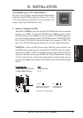
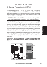
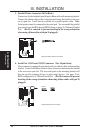
5. External Connectors
IMPORTANT: Ribbon cables should always be connected with the red stripe
on the Pin 1 side of the connector. The four corners of the
connectors are labeled on the motherboard. Pin 1 is the side closest to the
power connector on hard drives and floppy drives. IDE ribbon cable must be
less than 18in. (46cm), with the second drive connector no more than 6in. (15cm)
from the first connector.
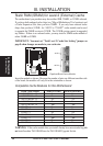
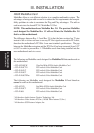
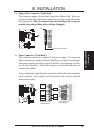
1. Keyboard Connector (5-pin female)
This connection is for a standard IBM-compatible keyboard. May also be
known as a 101 enhanced keyboard.
Connector Plug from Keyboard
Keyboard Connector (5-pin female)
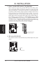
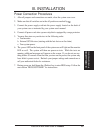
2. PS/2 Mouse Connector (6-pin block)
If you are using a PS/2 mouse, you must purchase an optional PS/2 mouse set
which connects to the 6 pin block and mounts to an open slot on your computer's
case. The system will direct IRQ12 to the PS/2 mouse if one is detected. If not
detected, expansion cards can use IRQ12. See PS/2 Mouse Control in BIOS
FEATURES SETUP.
PS/2 Mouse Module Connector
1: GND
2: DATA
3: NC
4: VCC
5: CLK
8: NC
1
3
4
2
5
8
1
3
4
2
5
8
(Connectors)
III. INSTALLATION
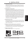
WARNING: Some pins are used for connectors or power sources. These are
clearly separated from jumpers in "Map of the Motherboard" on page 4. Plac-
ing jumper caps over these will cause damage to your motherboard.