


ASUS P/I-P55T2P4 User's Manual 21
III. INSTALLATION
(Connectors)
III. INSTALLATION
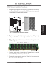
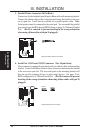
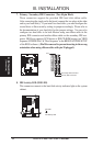
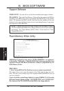
5. Floppy Drive Connector (34-pin block )
This connector supports the provided floppy drive ribbon cable. After con-
necting the single end to the board, connect the two plugs on the other end to
the floppy drives. (Pin 5 is removed to prevent inserting in the wrong ori-
entation when using ribbon cables with pin 5 plugged).
Floppy Drive Connector
Pin 1
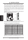
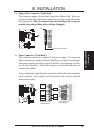
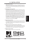
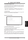
6. Power Connector (12-pin block)
This connector connects to a standard 5 Volt power supply. To connect the
leads from the power supply, ensure first that the power supply is not plugged.
Most power supplies provide two plugs (P8 and P9), each containing six wires,
two of which are black. Orient the connectors so that the black wires are
located in the middle.
Using a slight angle, align the plastic guide pins on the lead to their receptacles
on the connector. Once aligned, press the lead onto the connector until the
lead locks into place.
Power Plugs from
Power Supply
Power Connector
on Motherboard
PG
+5V
-12V
-5V
GND
+5V
+12V
P9
P8
RED
RED
RED
WHT
BLK
BLK
BLK
BLK
BLU
YLW
RED
ORG