


©American Audio® - www.AmericanAudio.us - DCD-PRO210™ Instruction Manual Page 12
GENERAL FUNCTIONS AND CONTROLS - PLAYER UNIT
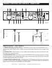
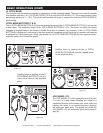
channel output and white jack represents the left channels output.
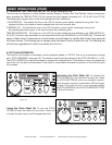
28. DRIVE 1 DIGITAL OUT - This jack sends a digital stereo out signal. Use this connection to cre-
ate near perfect copies of your disc to a Mini disc, CD-R, or any other recording device with a digital
input.
29. DRIVE 1 REMOTE JACK - Connect the supplied 8 pin cable from this jack to the remote control's
channel 1 remote connector. This will allow you to control the player functions with the remote unit.
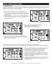
30. POWER CONNECTOR - This is the main power connection. Only use the supplied polarized
power cord. Use of any other power may result in sever damage to the unit. Be sure the local power
matches the unit’s required power.
31. VOLTAGE SELECTOR - Because power supplies vary from location to location a voltage selec-
tor switch has been incorporated in the unit's design. This switch can select a voltage input of 120v
or 220v to accommodate the two major power source. Always be sure to disconnect the power plug
before changing the voltage.
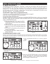
32. DRIVE 2 AUDIO OUT R & L - These jacks send a left and right analog mono output signal. Use
these jacks to send standard audio to a mixer or receiver. The red colored jack represents the right
channel output and white jack represents the left channels output.
33. DRIVE 2 DIGITAL OUT - This jack sends a digital stereo out signal. Use this connection to cre-
ate near perfect copies of your disc to a Mini disc, CD-R, or any other recording device with a digital
input.
34. DRIVE 2 REMOTE JACK - Connect the supplied 8 pin cable from this jack to the remote control's
channel 2 remote connector. This will allow you to control the player functions with the remote unit.