


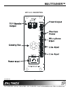
MULTITASKER™
400-0209-002
9
9
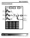
INSTALLING YOUR MT113-100/101 6
Step 1. Turn off power to the MultiTasker
enclosure.
Step 2. Slide the MT113-100/101 into an available
slot in the MultiTasker Enclosure in order
to connect to the bus. Make sure that the
MT113-100/101 card fits into place.
Step 3. Secure the card to the MultiTasker by
tightening the retainer screws located on
the top and bottom of the MT113-100/101
card.
Step 4. Turn on power to the MultiTasker.
Step 5. The fan on the card will turn on.
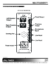
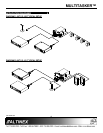
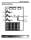
Step 6. Connect audio cables from the audio
source to the input connector of the
MT113-100/101. Connect the output
connectors of the MT113-100/101 to the
audio equipment through an audio cable.
Step 7. Starting from the left, identify the slot
number where the MT113-100/101 card is
plugged into the enclosure and note that it
is for RS-232 control.
OPERATION 7
7.1 RS-232 CONTROL
The MT113-100/101 has many advanced remote
control capabilities, which are accessible through
standard RS-232 communication. The actual
controlling can be accomplished through a
computer control system or any other device
capable of sending RS-232 commands.
7.1.1 RS-232 INTERFACE
The RS-232 commands, for the MT113-100/101
are in a simple ASCII character format.
1. Square brackets “[ ]” are part of the
command.
2. Use uppercase letters for all commands.
After processing a command, an OK or ER will
be returned as feedback if "F" is included at the
end of a command string.
Commands ending in "S" will be saved into
memory. Commands not ending in "S" will still
be executed but will not be restored when the
system is reset or powered OFF then ON.
7.2 DESCRIPTION OF COMMANDS
Each command consists of three parts:
Function, Card ID, and Unit ID.
[ Function , Card ID , Unit ID ]
Example: [VERC3U2]
VER = Function
C3 = Card ID or Group ID
U2 = Unit ID
For Function, see a detailed explanation under
each command description.
The Card ID is an assigned value. It is equal to
the enclosure slot number in which the card is
installed. The value can range from 1 to 4 up to
1 to 20 depending on the enclosure.
Card ID 0 (C0) is used for the controller. See
the MT100-100 User’s Guide for details.
The Group ID is a number representing a group
of cards defined with the [WR] command. When
using the Group ID, all cards in the group will
perform the given instruction.
Changing the position of a card will significantly
affect the commands recorded on software
definitions or third party control systems.
The Unit ID has a value from 0 to 9. Unit ID 0
should be used for single unit operation. If the
Unit ID is set to zero, each command may be
used without Ui. Use the command [SETU0],
as explained in the MT100-100 User’s Guide.
Example:
[VERC3]: For Unit ID Zero
[VERC3Ui]: For Unit ID other than Zero
[VERC3]: Equivalent to [VERC3U0]
1. [VER]
This command displays the software version
and card type for the MT113-100/101 card.