


72-EN
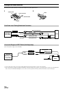
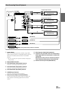
1 Antenna Extension Cable
2 Digital Output Terminal (Optical)
Use when combining fiber digital input compatible
products.
3 Remote Control Interface Connector
Connect to the remote control interface box.
4 Power Supply Connector
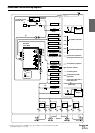
5 DC/DC Converter
• Do not install the converter at a location subjected to water
such as under the floor mat or air conditioner. This may cause
a malfunction.
• Do not bundle the DC/DC converter cable with other audio
cables. Doing so may induce noise into your system.
• Keep the DC/DC converter away from the Antenna cables and
the rear side of the unit, otherwise noise may be generated
when receiving radio broadcast.
6 Battery Lead (Yellow)
Connect this lead to the positive (+) post of the vehicle's
battery.
7 Fuse Holder (10A)
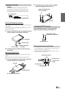
8 Ground Lead (Black)
Connect this lead to a good chassis ground on the
vehicle. Make sure the connection is made to bare metal
and is securely fastened using the sheet metal screw
provided.
9 Remote Control Output Lead (White/Brown)
Connect this lead to the remote control input lead. This
lead outputs the controlling signals from the remote
control.
! Remote Control Input Lead (White/Brown)
Connect the external Alpine product to the remote control
output lead.
" Reverse Lead (Orange/White)
Use only when a back-up camera is connected. Connect
to the plus side of the car's reverse lamp that lights when
the transmission is shifted into reverse (R).
Switches the video picture to the back-up camera. This is
linked with putting the car into reverse (R).
# Display Output Terminal
$ Remote IN/OUT Terminal
% Ai-NET Connector
Connect this to the output or input connector of other
product (CD Changer, Equalizer, etc.) equipped with Ai-
NET.
& Antenna Receptacle
( System Switch
When connecting an equalizer or divider using Ai-NET
feature, place this switch in the EQ/DIV position. When no
device is connected, leave the switch in the NORM
position.
• Be sure turn the power off to the unit before changing the
switch position.
) Remote Turn-On Lead (Blue/White)
Connect this lead to the remote turn-on lead of your
amplifier or signal processor.
~ Power Antenna Lead (Blue)
Connect this lead to the +B terminal of your power
antenna, if applicable.
+ Audio Interrupt In Lead (Pink/Black)
, Parking Brake Lead (Yellow/Blue)
Connect this lead to the power supply side of the parking
brake switch to transmit the parking brake status signals
to the IVA-D900.
- Foot Brake Lead (Yellow/Black)
Connect to the vehicle's foot brake lead or brake lamp
lead.
. Switched Power Lead (Ignition) (Red)
Connect this lead to an open terminal on the vehicle's
fuse box or another unused power source which provides
(+) 12V only when the ignition is turned on or in the
accessory position.
/ Fuse Holder (15A)
: Right Front (+) Speaker Output Lead (Gray)
; Right Front (–) Speaker Output Lead (Gray/Black)
< Right Rear (–) Speaker Output Lead (Violet/Black)
= Right Rear (+) Speaker Output Lead (Violet)
> Left Rear (+) Speaker Output Lead (Green)
? Left Rear (–) Speaker Output Lead (Green/Black)
@ Left Front (–) Speaker Output Lead (White/Black)
[ Left Front (+) Speaker Output Lead (White)
\ Monitor Extension Cable (Included)
] Subwoofer output Terminal
Connect the input lead of an amplifier for the subwoofer to
this terminal.
^ Rear output Terminal
Use when connecting an amplifier.
_ Front output Terminal
Use when connecting an amplifier.
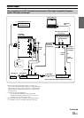
To prevent external noise from entering the audio system.
• Locate the unit and route the leads at least 10 cm away from
the car's electrical harness.
• Keep the battery power leads as far away from other leads as
possible.
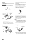
• Connect the ground lead securely to a bare metal spot (remove
any paint, dirt or grease if necessary) of the car chassis.
• If you add an optional noise suppressor, connect it as far away
from the unit as possible. Your Alpine dealer carries various
noise suppressors, contact them for further information.
• Your Alpine dealer knows best about noise prevention
measures so consult your dealer for further information.