


7
External Shunt Line and Load Connections
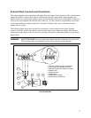
The Agilent supplied current shunt has both input (line) and output (load) connectors. The customer must
supply the cables to connect the ac lines to and from the external current shunt. Agilent supplies one
hooded cable cover for the input of the ac source and two hooded cable covers for the shunt. All three of
these covers are assembled and installed in the same way. It is the customer’s responsibility to use these
covers when making line cable connections. Note that a different cable cover is provided for the ac
output of the ac source.
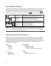
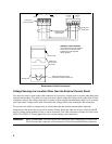
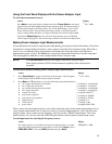
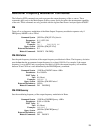
The following figure shows the Load and Line connectors on the external current shunt. Note the
location of the line, neutral and ground connectors and connect your cables accordingly. Note that the
connections on the output of the ac source are not in the same order on the barrier block as on the shunt
barrier block.
WARNING: SAFETY HAZARD You must replace the cable hoods after completing all connections.
This is because the screw terminals will be at line potential during operation.
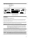
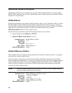
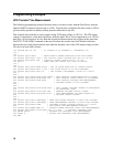
Line Connections
1
2
3
5
6
4
8
7
3. GROUND CONNECTION (GRN/YEL OR GRN)
2. LINE CONNECTION (BROWN OR BLACK)
1. NEUTRAL CONNECTION (BLUE OR WHITE)
4. POWER CORD
5. CONNECTOR NUT
6. RUBBER BOOT
7. POWER SAFETY COVER
8. STRAIN RELIEF CONNECTOR
LN