


5
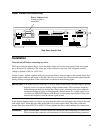
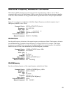
Rear Panel Connections
Power Analyzer input.
Connector plug is
removable.
L
IN
E
R
A
T
IN
G
HP-IB
F
L
T
I
N
H
++
-
_
_
C
O
M
_
_
C
O
M
O
1
_
O
1
_
SENSE
W
A
R
N
IN
G
300 V
A
C
M
A
X
T
O
_
_
_
R
S
2
3
2
L 2( N )
L
1
O
P
T
I
O
N
S
C
A
U
T
IO
N
W
A
R
N
I
N
G
TRIGGER
O
U
T
1
I
N
1
. . . . .
. . . .
LO HI LO HI
V
SENSE
I
SENSE
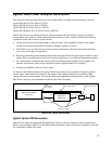
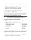
Rear Panel, Overall View
Installation
Turn the unit off before connecting any wires.
The Power Analyzer input to the ac source has both voltage and current sense inputs. Each sense input
has a HI and a LO connection. The center pin of the connector is not used. The maximum isolation
voltage to ground is 300 Vac (±425 Vdc).
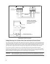
Use the 1-meter, Agilent supplied cable and connect the Power Analyzer input to the external shunt. Note
that the cable connectors are keyed so that the cable will only fit one way. Disconnect the cable from the
unit by pulling it straight back. Cable connections are shown in the following figure.
IMPORTANT: You should always connect the V SENSE inputs for the Power Analyzer input to operate
properly, even if you are not making voltage measurements. This is because frequency
measurements are made by sensing the voltage signal, and many of the power analyzer
measurements depend on an accurate frequency measurement. If a voltage signal is not
available, use SENSe:FREQuency:SOURce (or its front panel equivalent) to select and
measure the frequency from the current signal instead.
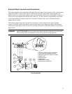
If the Agilent supplied cable is too short, you may open the cable ends and replace the wiring in the cable
with longer wires. Install the new cable in the same way as the original cable. The cable connectors
accepts wire sizes from AWG 22 to AWG 12. Firmly tighten the screws when making wire connections.
WARNING: SAFETY HAZARD You must replace the cable hoods after completing all connections.
This is because the connector screw terminals will be at line potential during operation.