


22
Verification and Calibration for Option 020/022
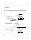
This section includes verification and calibration procedures for the Agilent Dual Power Analyzer Option
020/022. Add these procedures to those described in Appendix B of the AC Source User’s Guide.
The verification procedures do not check all the operating parameters, but verify that the ac source is
performing properly. Performance Tests, which check all the specifications of the ac source, are given in
the applicable ac source Service Manual.
Because the output of the ac source must be enabled during verification or calibration, proceed with
caution, since voltages and currents will be active at the output terminals.
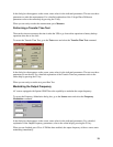
Important Perform the verification procedures before calibrating your ac source. If the ac source
passes the verification procedures, the unit is operating within its calibration limits and
does not need to be re-calibrated.
WARNING LETHAL VOLTAGES. Ac sources can supply 424 V peak at their output. DEATH
on contact may result if the output terminals or circuits connected to the output are
touched when power is applied. These procedures must be performed by a qualified
electronics technician or engineer trained on this equipment.
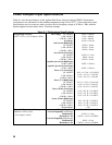
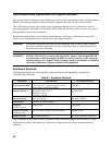
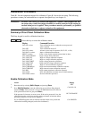
Equipment Required
The equipment listed in the following table, or the equivalent to this equipment, is required for
verification and calibration.
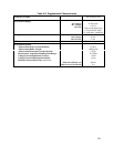
Table B-1. Equipment Required
Equipment Characteristics Recommended Model
5-pin connector plug
This connector is supplied with the ac source
when ordered with Option 020/022.
0360-2681
Digital Voltmeter
Resolution: 10 nV @ 1 V
Readout: 8.5 digits
Accuracy: >20 ppm
Agilent 3458A
Current Monitor
1
0.01
Ω
,
±
200 ppm,
Guildline 7320/0.01
Load Resistor
30 ohm, 100 Watts minimum
Capacitor
(calibration only)
1.0
µ
F, 50 V
0160-3490
Function Generator
(calibration only)
50 mV, 500 mV, 60 Hz sinewave capability Agilent 33120A
GPIB Controller
Full GPIB capabilities HP Series 200/300 or equivalent
1
The 4- terminal current shunt is used to eliminate output current measurement error caused by voltage
drops in the load leads and connections. Connect the voltmeter directly to these current-monitoring
terminals.