


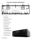
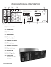
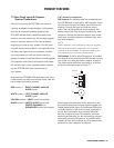
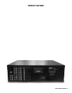

1.2 Rear Panel Inputs & Outputs -
System Connections
Like the front panel, the GTP-830’s rear panel is
carefully arranged to make hookup, configuration,
and use as simple as possible. However, the
GTP-830’s extraordinary capabilities take some
study to use most effectively. We strongly suggest
that you read this section of the manual before
beginning to hook up your system. You will save
yourself much time and effort if you carefully think
out what you expect from your system: consider
the components you will use, where they’ll be
placed, and how you will want them to work together.
The diagrams and notes in this section will proba-
bly answer most of your questions about interfac-
ing the GTP-830 with other components in
your system.
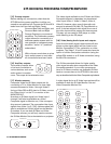
Note that the GTP-830’s RCA-style jacks have color-
coded centers to make connections easier. Use this
key to help route cables properly:
RED centers = RIGHT CHANNEL ANALOG
AUDIO inputs
WHITE centers = LEFT CHANNEL ANALOG
AUDIO inputs
YELLOW centers = VIDEO inputs (composite)
BLACK centers = DIGITAL AUDIO inputs and
CENTER CHANNEL and
SUBWOOFER inputs and outputs
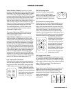
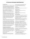
[14] Antenna connections:
AM Antenna: An AM loop antenna is supplied with
the GTP-830 and is required for AM reception. Open
the clip terminal lever and insert the wire from the
antenna. Closing the lever will lock the wire in
place. Test various positions for the antenna, but
always ensure the loop is placed vertically for best
reception. Placing the antenna close to large metal
items such as metal shelves or radiators may inter-
fere with reception.
NOTE:
When reception is not satisfactory using the supplied
AM loop antenna alone, connection of an external
antenna is recommended. The antenna cable to the
loop antenna must not exceed three meters.
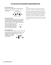
FM Antenna: A ribbon wire FM antenna is included
and should be connected to the FM connector at the
rear of the unit using the ‘balun’ adapter supplied.
The ribbon aerial should be mounted on a vertical
surface and placed so that it forms a ‘T’.
Experiment with placement of the antenna to find
the position that gives the best signal strength and
lowest background noise. An inadequate FM signal
normally results in high levels of hiss, especially in
stereo, and interference from external electrical
sources. In areas of poor FM reception, the tuner
section’s performance can be improved by using an
externally mounted FM antenna. A qualified aerial
installer will be able to advise and fit a recommend-
ed aerial for your reception conditions.
PRODUCT FEATURES
FM
gnd
AM
antenna
ADCOM OWNER’S MANUAL | 15