


19
English
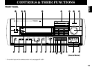
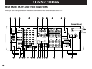
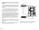
1 Antenna Connection Terminals
Connect the included indoor FM antenna to the FM ANT
terminal and connect the included AM loop antenna to the AM
ANT and GND terminals. To heighten safety and reduce
interference, connect the GND terminal to a good earth ground.
For improving reception quality, you can connect outdoor FM
and/or AM antenna to these terminals (See pages 27 to 29 for
details.)
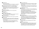
2 FREQUENCY STEP Switch (General Model only)
Because the interstation frequency spacing differs in different
areas, set this switch to the position suitable for the frequency
spacing in your area.
Before sliding this switch, disconnect the AC power plug of this
unit from the AC outlet.
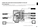
3 AUDIO SIGNAL Connection Jacks (for Audio Source
Equipment)
Connect the inputs and/or outputs of your audio equipment.
4 AUDIO/VIDEO SIGNAL Connection Jacks (for Video Source
Equipment)
Connect the audio and video inputs and/or outputs of your
video equipment. In place of the VIDEO jacks, the S VIDEO
jacks can be used for higher resolution and improved picture
quality if your VCR, monitor, etc. are equipped with S-VIDEO
connectors.
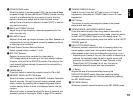
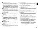
5 CENTER OUTPUT Jacks
Center-channel line outputs. Can be connected to input jack(s)
of one or two external power amplifier(s) to drive the center
speaker(s).
6 CENTER SPEAKERS Terminals
When using the built-in center-channel amplifier, connect one
or two center speakers here.
7 Center Speaker Switch
Set to “C + D” when using two center speakers, or to “C OR D”
when using only one center speaker.
8 FRONT EFFECT SPEAKERS Terminals
When using the built-in front effect-channel amplifier, connect
the front effect speakers here.
9 REAR SPEAKERS Terminals
When using the built-in rear-channel amplifier, connect the rear
speakers here.
0 VOLTAGE SELECTOR (General Model only)
Be sure to set to the line voltage in your area before applying
power. Consult your dealer if unsure of the correct setting.
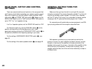
A GND Terminal
Connects the ground wire of the turntable to produce minimum
hum. In some cases, however, better results may be obtained
with the ground wire disconnected.
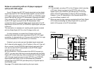
B PCM/ DIGITAL IN (COAXIAL and OPTICAL) jacks
Can be connected with audio/video units that have a coaxial or
optical digital output jack. Connect a unit that is connected to
the DVD/LD AUDIO/VIDEO SIGNAL connection jacks to the
DVD/LD COAXIAL or OPTICAL jack.
Connect a unit that is connected to the TV/DBS AUDIO/VIDEO
SIGNAL connection jacks to the TV/DBS COAXIAL jack.
* If, for example, your LD player has an AC-3 RF output jack
and no digital output jack for AC-3 discrete audio signals,
connect the AC-3 RF output jack to the DVD/LD COAXIAL or
OPTICAL jack of this unit by way of an RF demodulator
(separate purchase).