


14
2
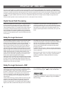
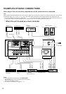
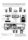
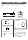
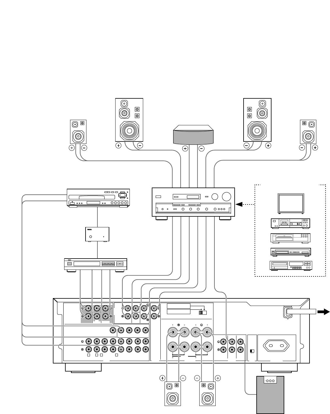
When connecting with your existing integrated amplifier or receiver
which cannot receive signals with the Dolby Digital (AC-3) decoded
(This diagram shows this unit is connected with the Yamaha DSP-A2070 which is equipped with the digital sound field
processor, the Dolby Pro Logic Surround Decoder and seven-speaker driving amplifiers.)
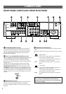
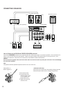
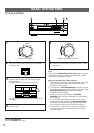
MONITOR
OUT
DVD/LD TV/DBS
IN OUT
VCR
VIDEO SIGNAL
CD
(LINE 1)
TAPE
( MD )
DVD/LD TV/DBS
VCR
TAPE
PB
REC
OUT
IN OUT
AUDIO SIGNAL
1
3 4
MAIN
TUNER
(LINE 2)
2
(SURROUND)
REARCENTERMAIN
SUB
WOOFER
INPUT
from
AMP/RECEIVER
PREOUT
MAINS
SPEAKERS
OUTPUT
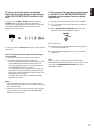
INPUT OUTPUT
l0 dB 0 dB
l
MAIN
LEVEL
SINGLE:8ΩMIN./SPEAKER
DUAL:4ΩMIN./SPEAKER
8ΩMIN./SPEAKER
CENTER
REAR
SINGLE:4ΩMIN./SPEAKER
DUAL:2ΩMIN./SPEAKER
6ΩMIN./SPEAKER
CENTER
REAR
IMPEDANCE SELECTOR
REAR CENTER
SUB
WOOFER
DUAL
(SURROUND)
DUAL
CAUTION
SEE INSTRUCTION MANUAL FOR CORRECT SETTING.
DUAL DUAL
SINGLE
REAR
CENTER
I00W MAX.
SWITCHED
AC OUTLET
6CH DISCRETE
INPUT
REARCENTERMAIN
SUB
WOOFER
(SURROUND)
CENTER IN
MAIN IN
REAR OUT
CENTER OUT
LOW PASS
MAIN OUT
AUDIO OUT
VIDEO OUT
AC-3 RF OUT
AC-3 RF IN
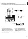
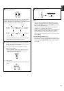
Main speaker
Front effect speaker
Center speaker
Rear speakers
Subwoofer
System
Front effect speaker
Main speaker
Dolby Digital (AC-3) Decoder
RF demodulator
(YAMAHA APD-1 etc.)
LD player etc.
Amplifier or
receiver
To AC
outlet
Audio/Video equipment
(Europe model)
Left
Left
Right
Right
LeftRight
Notes
●
For the connections to this unit’s 6CH DISCRETE INPUT
terminals, refer to page 11.
●
For the connections of rear speakers and subwoofer(s) to
this unit, refer to page 12 – 13.
●
If you select this connecting way, the PROCESSOR
SELECTOR switch on the front panel must be normally set
to the “EXTERNAL” position. When you will play a source
on the LD player etc. (connected to this unit) with the Dolby
Digital (AC-3) decoded, set the PROCESSOR SELECTOR
switch to the “INTERNAL” position.