


10
MONITOR
OUT
DVD/LD TV/DBS
IN OUT
VCR
VIDEO SIGNAL
CD
(LINE 1)
TAPE
( MD )
DVD/LD TV/DBS
VCR
TAPE
PB
REC
OUT
IN OUT
AUDIO SIGNAL
1 3 4
MAIN
TUNER
(LINE 2)
2
(SURROUND)
REAR
CENTERMAIN
SUB
WOOFER
INPUT
from
AMP/RECEIVER
PREOUT
OUTPUT OUTPUT
l0 dB 0 dB
l
MAIN
LEVEL
6CH DISCRETE
INPUT
REAR
CENTERMAIN
SUB
WOOFER
(SURROUND)
I00W MAX.
SWITCHED
AC OUTLET
MAINS
INPUT
OUTPUT
OUTPUT
LINE OUT
LINE IN
VIDEO OUT
AUDIO OUT
AUDIO OUT
AUDIO IN
VIDEO IN
VIDEO OUT
AUDIO OUT
VIDEO OUT
MAIN IN
VIDEO IN
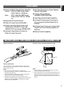
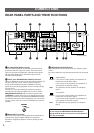
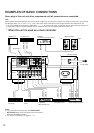
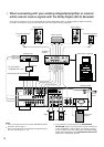
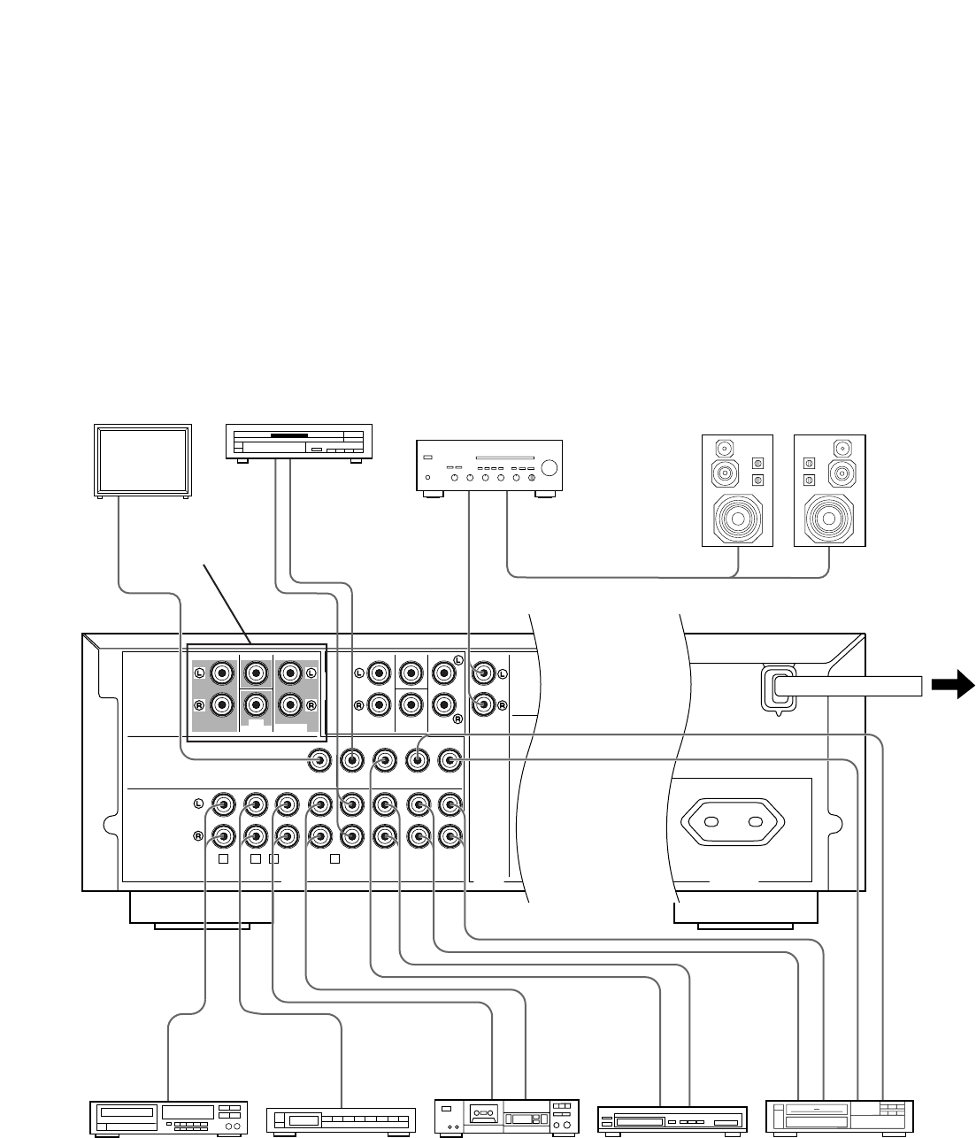
EXAMPLES OF BASIC CONNECTIONS
Never plug in this unit and other components until all connections are completed.
Note
When making connections between this unit and other components, be sure all connections are made correctly, that is to say L (left)
to L, R (right) to R, “+” to “+” and “–” to “–”. Also, refer to the owner’s manual for each component to be connected to this unit.
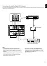
* If you have YAMAHA components numbered as
1, 2, 3, etc. on the rear panel, connections can be made easily by making sure
to connect the output (or input) terminals of each component to the same-numbered terminals of this unit.
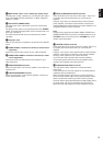
1
When this unit is used as a main controller
(Europe model)
To AC outlet
Monitor TV
Amplifier
(for driving main speakers)
Video cassette recorderTV/Satellite tuner
Tape deck,
MD recorder, etc.
CD player
LD player etc.
Main speakers
Left
Right
Tuner
Notes
●
If you select this connecting way, the PROCESSOR
SELECTOR switch on the front panel of this unit must be
set to the “INTERNAL” position.
●
For speaker connections, see page 12 – 13.
See page 11.