


E-21
PREPARATIONS
English
CONNECTIONS
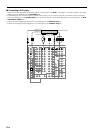
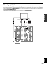
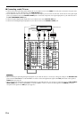
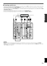
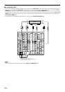
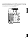
Connecting video components
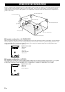
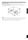
Before you connect any components, disconnect the power supply to all the components you plan to connect including this unit and deter-
mine which jacks are for the left and right channels and for input and output. After you finish all connections, check them again to make sure
they are correct.
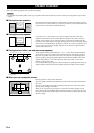
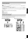
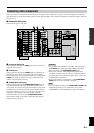
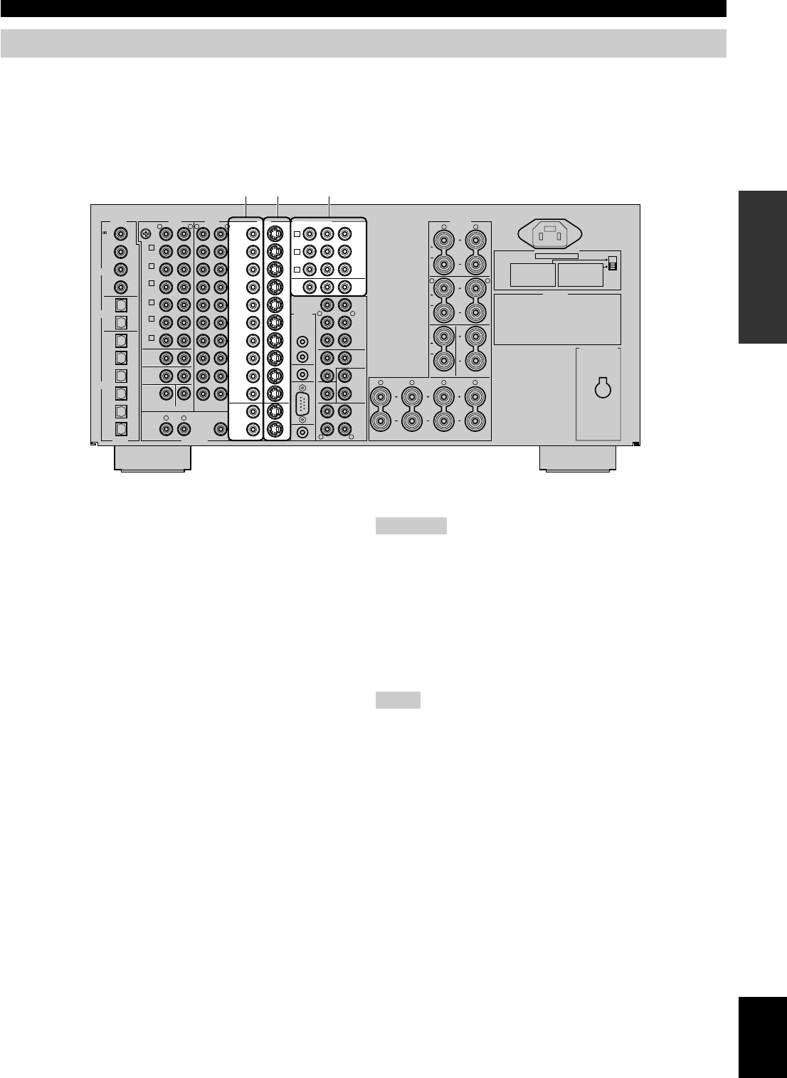
■ About the video jacks
There are three types of video jacks.
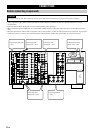
AC OUTLETS
IMPEDANCE SELECTOR
SET BEFORE POWER ON
MAINS
SWITCHED
SPEAKERS
R L
FRONT
R
R L
L
REAR
CENTER
MAIN
B
R L
A
REAR CENTER
(
SURROUND
)
CAUTION
SEE INSTRUCTION MANUAL FOR CORRECT SETTING.
A
DVD
COMPONENT VIDEO
AUDIOAUDIODIGITAL
ZONE 2 OUTDIGITAL
VIDEO
B
D–TV
/LD
C
SAT
MONITOR
OUT
FRONT
IN
FRONT
OUT
REAR
(
SURROUND
)
SUB
WOOFER
SPLIT
MONO
REAR CTR
IN
OUT
REMOTE 1
IN
CTRL
OUT
+12V
10mA
MAX.
RS–
232C
REMOTE 2
CENTER
IN
CENTER
OUT
YP
B
/C
B
P
R
/C
R
R L
PREOUT/MAIN IN
CONTROL
MAIN
IN
MAIN
OUT
R L
VIDEO
DVD
PHONO
GND
CD
S VIDEO
LRR L
CABLE
SAT
IN
VCR 1
OUT
IN
VCR 2
OUT
IN
VCR 3
/DVR
OUT
VIDEO
6CH INPUT
CENTER
SUB
WOOFER
VCR 3
/DVR
1
MONITOR
OUT
2
D–TV
/LD
L
SURROUND
MAIN
R
1
TUNER
CD–R
2
IN
(PLAY)
3
OUT
(REC)
4
MD/TAPE
IN
(PLAY)
3
OUT
(REC)
4
OPTICAL
IN
OPTICAL
OUT
COAXIAL
IN
w
D–TV
/LD
0
MD/
TAPE
6
SAT
q
DVD
9
CD–R
8
CD
7
CD–R
5
CABLE
4
DVD
3
CD
2
LD
LD
RF
(AC–3)
1
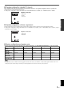
VOLTAGE SELECTOR
FRONT
REAR
REAR CENTER
CENTER
MAIN A OR B
A + B
:
6Ω
MIN. /SPEAKER
:
4Ω
MIN. /SPEAKER
:
4Ω
MIN. /SPEAKER
:
4Ω
MIN. /SPEAKER
:
4Ω
MIN. /SPEAKER
:
8Ω
MIN. /SPEAKER
FRONT
REAR
REAR CENTER
CENTER
MAIN A OR B
A + B
:
8Ω
MIN. /SPEAKER
:
8Ω
MIN. /SPEAKER
:
8Ω
MIN. /SPEAKER
:
8Ω
MIN. /SPEAKER
:
8Ω
MIN. /SPEAKER
:
16 Ω
MIN. /SPEAKER
12 3
1 Composite VIDEO jack
Video signals input through the VIDEO jacks are the conventional
composite video signals.
2 S VIDEO jack
Video signals input through the S VIDEO jacks are separated into
luminance (Y) and color (C) video signals. The S-video signals
achieve high quality color reproduction. When you are using the S
VIDEO jacks, check the details in the owner’s manual that came
with the component being connected.
3 COMPONENT VIDEO jacks
Video signals input through the COMPONENT VIDEO jacks are
separated into luminance (Y) and color difference (PB/CB, PR/CR)
video signals. The jacks are also separated into three for each signal.
The labels of the component video jacks may be different depend-
ing on the component (e.g. Y, C
B, CR / Y, PB, PR / Y, B-Y, R-Y/ etc.).
Component video signals provide the best quality in picture
reproduction. When you are using the COMPONENT VIDEO
jacks, check the details in the owner’s manual that came with the
component being connected.
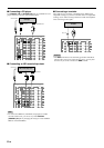
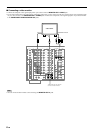
Cautions
• Use a commercially available S-video cable when connecting to
the S VIDEO jacks, and commercially available video cables
when connecting to the COMPONENT VIDEO jacks.
• Each type of video jack works independently. Signals input
through the composite video, S-video, and component jacks are
output through the corresponding composite video, S-video, and
component jacks respectively.
• If your video monitor is connected only to the COMPONENT
VIDEO jacks of this unit, the OSD is not shown.
Note
• You can designate the input for the COMPONENT VIDEO A, B
and C jacks according to your component by using “8 I/O
ASSIGNMENT” on the SET MENU (see page 58 for details).