


E-11
INTRODUCTION
English
CONTROLS AND FUNCTIONS
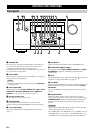
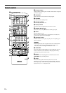
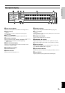
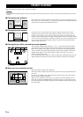
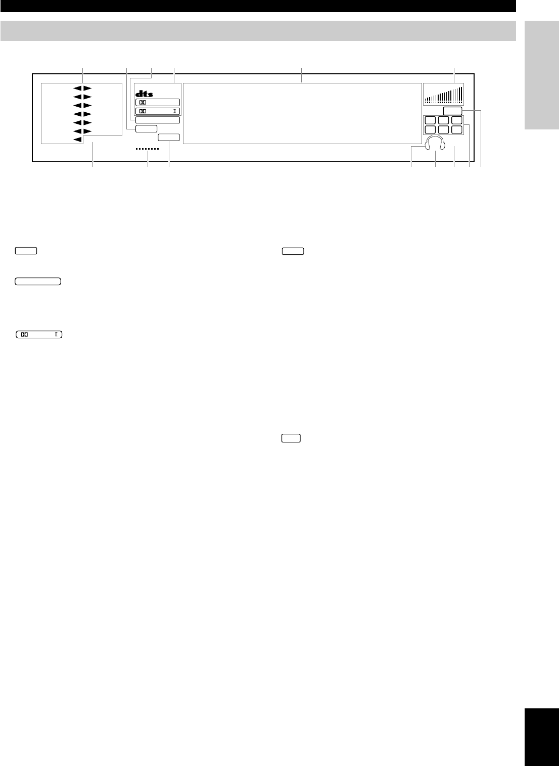
Front panel display
1 Input source indicator
Shows the current input source with the arrow-shaped cursor.
2
DSP
indicator
Lights up when you select a digital sound field program.
3
96kHz
/
24bit
indicator
Lights up when the DTS 96/24 signal is input to this unit.
4 Processor indicators
When any function of DTS, MATRIX, DISCRETE, g,
and
PRO LOGIC
/
is activated, its indicator lights up.
5 Multi-information display
Shows the current DSP program and other information when
adjusting or changing settings.
6 VOLUME level indicator
Indicates the volume level.
7 SLEEP indicator
Lights up while the sleep timer is on.
D–TV/LD DVD
CABLE
MD/TAPE
SAT
CD–R
VCR 1 TUNER
VCR 2 CD
VCR3/DVR
PHONO
V–AUX
SLEEP
VIRTUAL
MATRIX
DISCRETE
DIGITAL
PRO LOGIC
/
96kHz
/
24bit
DSP
PCM
VOLUME
LFE
L C R
RL
SP
AB
SILENT
RC RR
1
789 0qwer
234 5 6
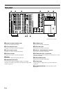
8 VIRTUAL indicator
Lights up when using Virtual CINEMA DSP (see page 49).
9
PCM
indicator
Lights up when this unit is reproducing PCM (Pulse Code Modula-
tion) digital audio signals.
0 Headphones indicator
Lights up when headphones are connected.
q SPEAKERS A/B indicator
Lights up according to which set of main speakers are selected.
Both indicators light up when both sets of speakers are selected.
w SILENT indicator
Lights up when headphones are connected with the sound effect
(see “SILENT CINEMA DSP” on page 49).
e Input channel indicator
Indicates the channel components of input signals being received.
r
LFE
indicator
Lights up when the input signal contains the LFE signal.