


Front and Rear of Unit
7
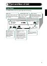
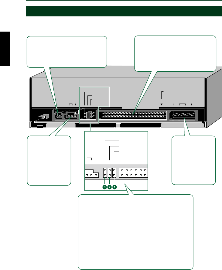
Rear Panel
The CRW2100E drive’s rear panel features the following:
AUDIO OUT
DIGITAL ANALOG
DG
CSEL
SLAVE
MASTER
RGL
+
5V
DC INPUT
G
+
12
V
1
IDE
INTERFACE
CONNECTOR
CSEL
SLAVE
MASTER
L
G
IO OUT
ANALOG AUDIO
OUT connector
Connect one end
of the 4-pin audio
cable to this and
the other end to
your computer’s
sound card or
built-in audio.
DC INPUT
connector
Insert the power
connector from your
computer’s power
supply in this
socket to feed
power to the drive.
IDE INTERFACE connector
Insert the connector of the IDE cable
here. Make sure you align the red line
of the ribbon cable with pin 1 of the
drive’s connector, marked “IDE
INTERFACE CONNECTOR 1.”
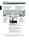
DIGITAL AUDIO OUT connector
If your sound card has a digital audio
input, you can connect this connector
to that digital input using a digital
audio cable (sold separately).
1 MASTER jumper switch
Plug a plastic shunt into this jumper switch if you are
connecting the master CRW2100E using an IDE
cable.
2 SLAVE jumper switch (default setting)
Plug a plastic shunt into this jumper switch if you are
connecting the slave CRW2100E using an IDE cable.
3 CSEL jumper switch
If your computer supports the CSEL function, plug a
plastic shunt into this jumper switch to have the
computer automatically select master or slave for the
CRW2100E.
n Usually, use the MASTER or SLAVE jumper switch because the CSEL function may
sometimes create a conflict. Refer to the documentation that came with your computer
to check whether the computer supports the CSEL function.