


18
AUDIOGRAM 3 Owner’s Manual
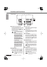
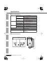
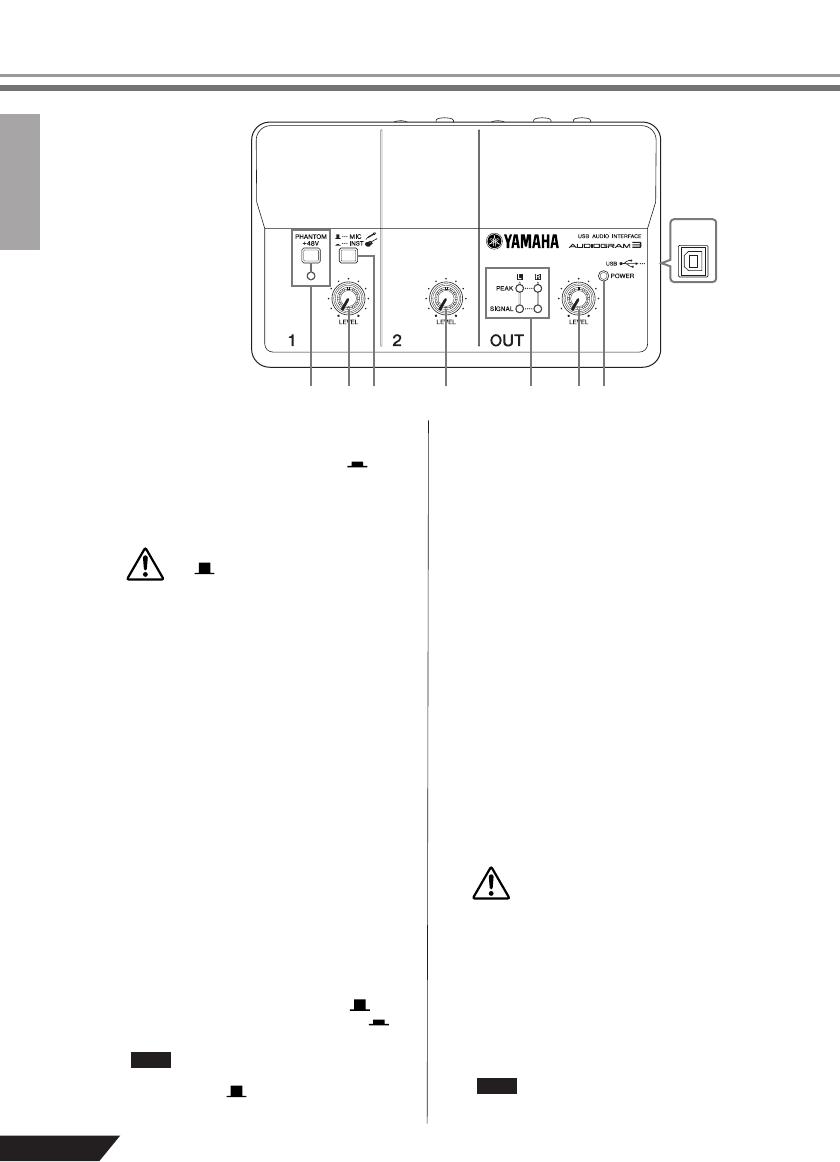
Controls and Functions
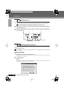
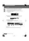
1
PHANTOM +48V Switch/Indicator
This switch toggles phantom power on and
off. If you set the switch on ( ), the
AUDIOGRAM supplies phantom power to
the MIC/INST jack (XLR-type)
8
. Tu rn this
switch on when using a phantom-powered
condenser microphone.
• Be sure to leave this switch off
() if you do not need phantom
power.
• When turning the switch on, be
sure that only a condenser micro-
phone is connected to the MIC/
INST input jack. Other devices
may be damaged if connected to
phantom power. This precaution
does not apply to balanced
dynamic microphones or instru-
ments with the phone jack, how-
ever, as these will not be affected
by phantom power.
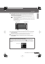
•To prevent damage to speakers,
be sure to turn off audio system
(monitor speakers) before turn-
ing this switch on or off. We also
recommend that you set the OUT
LEVEL control to the minimum
position. Neglect of these pre-
cautions may result in large
noise bursts that may damage
your equipment, your ears, or
both.
2
MIC/INST Switch
Set this switch according to the type of
device connected. Select MIC ( ) if a
microphone is connected, or INST ( ) if
an electric guitar or bass is connected.
If a device is not connected to the
MIC/INST jack, set this switch to
MIC ( ). Otherwise noise may
occur.
3
LEVEL Controls
Adjusts the level of the channel signal. Use
these controls to adjust the balance
between the channels.
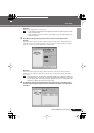
4
POWER Indicator
This indicator lights when power is applied
to the AUDIOGRAM interface via the USB
cable (supplied) that connects it to the
computer.
5
Level Indicators
These indicators show signal levels prior to
the OUT LEVEL control
6
. The SIGNAL
LED lights when a signal is present, and the
PEAK LED lights when the signal reaches
or exceeds clipping level. Adjust the input
channel LEVEL controls
3
so that the
PEAK LEDs flash only briefly on occasional
high-level peaks or not at all.
6
OUT LEVEL Control
Adjusts the signal level sent to the STE-
REO OUT jacks
0
. This allows you to
adjust the overall volume without changing
the relative volume balance among the
channels.
When connecting or disconnecting
the USB or audio cables be sure to
turn the OUT LEVEL control all the
way down.
7
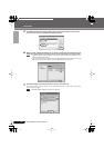
USB Connector
Connects the AUDIOGRAM interface to a
USB port on your computer via the sup-
plied USB cable. In addition to transferring
audio data between the AUDIOGRAM
interface and the computer, the USB cable
supplies power from the computer to the
AUDIOGRAM interface.
Yamaha recommends that you
use a USB cable with a length of
1.5 meter or less.
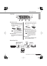
u
t yee w rq
Control Panel
CAUTION
NOTE
CAUTION
NOTE