


ACD1 Reference Manual
20
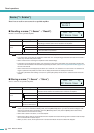
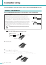
Connector wiring
You can connect a lamp etc. to the rear panel [FAULT OUTPUT] connector to
indicate that an abnormality has occurred.
The [FAULT OUTPUT] connector consists of NO (Normally Open), C (Common), and
NC (Normally Closed). The [FAULT OUTPUT] connector is a relay circuit, and oper-
ates as follows.
The relay contacts used in the [FAULT OUTPUT] connector are rated for a load of 1A, DC 30V. Do not apply a load that
exceeds this rating.
Use Amp Editor to make settings for the [FAULT OUTPUT] connector.
Euroblock plugs are used for the [FAULT OUTPUT] connector. Euroblock connection methods are described in “Euroblock
plug connection” (page 18) in this manual.
• In Amp Editor’s [Device Setup] menu ➝ [Alert Setup], you can set Type to Fault so that a fault can be indicated by a con-
nected lamp, etc. For details on making settings, refer to the “Amp Editor owner’s manual.”
• The relay contacts are rated for a resistive load of 1A, DC 30V. Do not apply a load that exceeds this rating.
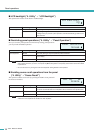
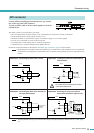
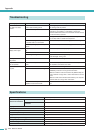
FAULT OUTPUT connector
Normal state Abnormal state Powered-off
NO Open Closed Closed
NC Closed Open Open
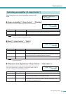
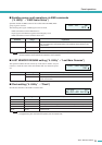
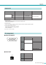
● Example : Using an LED to indicate normal/fault status of the ACD1
NOTE
C
NC
NO
C
NC
NO
Normal state
Lit
Powered-off / Abnormal state
ACD1 ACD1
Unlit
Unlit
Lit
CAUTION