


ACD1 Reference Manual
18
Connector wiring
This section explains how to wire the [GPI] and [FAULT OUTPUT] connectors located on the ACD1’s rear panel.
Be sure to use the supplied Euroblock connector. If you lose the connector, contact your Yamaha dealer.
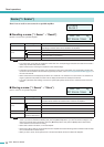
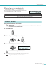
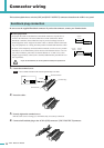
1. Loosen the terminal screws.
• Use a slotted screwdriver with a blade approximately 2 mm wide.
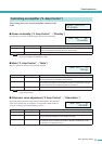
2. Insert the cables.
3. Securely tighten the terminal screws.
Pull the cables (not too strongly) to confirm that they are securely connected.
4. Connect the Euroblock plug to the ACD1’s [GPI] connector / [FAULT OUTPUT] connector.
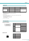
Euroblock plug connection
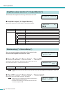
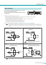
● Cable preparation
•To prepare the cable for attachment to a Euroblock connector, strip the wire as
shown in the illustration, and use stranded wire to make connections. With a
Euroblock connection, the stranded wire may be prone to breakage because of
metal fatigue due to the weight of the cable or due to vibration. When rack-mount-
ing your equipment, use a lacing bar when possible to bundle and fasten the cables.
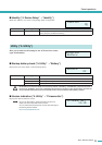
• If cables will be frequently connected and disconnected, as in the case of a portable
installation, we recommend that you use ferrules with insulation sleeves. Use a fer-
rule whose conductor portion has an external diameter of 1.3 mm or less, and a
length of approximately 5 mm (such as the AI0,5-6WH made by the Phoenix Con-
tact corporation).
• If you use stranded wire, do not tin (plate with solder) the exposed end.
approx.
5 mm
approx.
5 mm
1.3 mm
or less
CAUTION
NOTE
Euroblock plug
Slotted screwdriver
Ter minal screw
Loosen
2 mm