


ACD1 Reference Manual
19
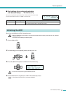
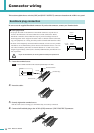
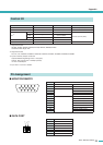
Connector wiring
Connect GPI (General Purpose Interface) devices (e.g., control-
lers) to the rear panel [GPI] connector.
You can use GPI to send or receive control signals to or from an
external device.
The ACD1 provides 4-port input and 4-port output.
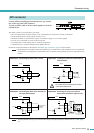
• The +V terminals have an output voltage of 5 V. A maximum total of 100 mA of current can be drawn.
• The IN terminals detect voltage changes from 0 V to 5 V.
• The OUT terminals are open-collector outputs. A maximum voltage of +12 V can be applied.
•For each port, a maximum of 75 mA of current can flow.
• Use Amp Editor to make settings such as parameter assignments.
•A Euroblock plug is used for connection to the [GPI] connector.
Euroblock connection methods are described in “Euroblock plug connection” (page 18) in this manual.
• By specifying the input/output channels in Amp Editor, you can recall scenes or edit parameters from a connected exter-
nal GPI device, or send signals to an external GPI device. For details on making settings, refer to the “Amp Editor owner’s
manual.”
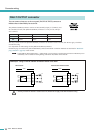
•To adjust (calibrate) the range over which the input voltage to the [GPI] connector is detected, refer to “5. Utility” (page
13).
GPI connector
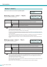
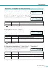
● Example : Controlling the ACD1 from a switch ● Example : Lighting the LED of an external device
from the ACD1
• Do not allow the current flowing from the OUT
connector to exceed 75 mA.
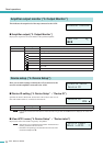
● Example : Controlling the ACD1 via a 10k ohm lin-
ear taper potentiometer
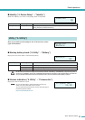
● Example : Switching the relay of an external
device from the ACD1 to light an LED
GND OUT GND IN Voltage
NOTE
IN
+V
+5V
A/D
CPU
100k
ACD1
OUT
+V
+5V
CPU
10
Max. 75 mA
ACD1
CAUTION
IN
+V
+5V
GND
A/D
CPU
100k
Continuously
variable
volume
ACD1
OUT
+V
+
–
+5V
CPU
10
ACD1
Max. 75 mA
NOTE