


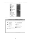
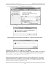
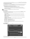
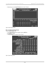
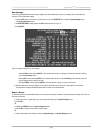
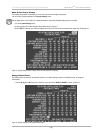
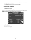
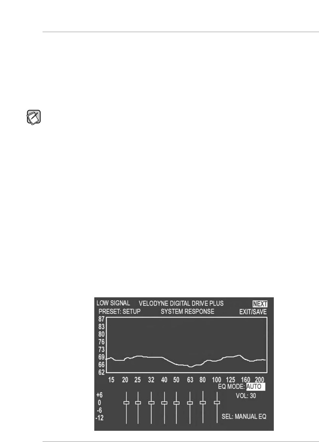
SYSTEM RESPONSE SCREEN
F
rom the
I
ntroductory
s
creen you can get to the
S
ystem Response
s
creen which is used to display the frequency response graph for the
subwoofer’s output. See Figure 3. See the Remote Control Button Sequence Commands table on page 25 for the button sequence.
The
System Response screen has the following information and features on it:
• A system response graph that shows the subwoofer’s low frequency output from 15 to 200 Hz.
• A moving screen pixel marks on the frequency response curve the current frequency of the sweep tone that is playing.
• 8 parametric filters each of which can be used at its current frequency or adjusted to a frequency and Q you desire between 15
a
nd 200 Hz when in Manual-EQ mode.
T
he filter level range is -13db to +6dB although the screen is only marked from -12dB to +6dB.
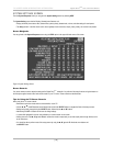
Status Messages
Status messages appear in the upper left hand corner of the TV screen. In Figure 3, the status message is LOW SIGNAL. The following
status messages appear in this position on the TV screen:
•
MIC?: The subwoofer is receiving no signal from the microphone. Microphone is not connected, or either the microphone
or the cable is damaged.
•
SYNCING: The subwoofer is trying to synchronize its frequency measurement with the frequency of the sweep tone being
played through your audio system.
•
SYNCED: The subwoofer has synchronized its frequency measurement with the frequency of the sweep tone being played
through your audio system.
•
LOW SIGNAL: The receiver output level is too low to perform optimization. Turn up the receiver volume. After 6 sweeps with
this condition, the subwoofer will reboot.
•
HIGH SIGNAL: The receiver output level is too high to perform optimization. Turn down the receiver volume.
•
VOL..: Auto-EQ
PLUS
is adjusting subwoofer volume.
•
CRS..: Auto-EQ
PLUS
is adjusting subwoofer crossover frequency.
•
SLP..: Auto-EQ
PLUS
is adjusting subwoofer crossover filter slope.
•
PHS..: Auto-EQ
PLUS
is adjusting subwoofer phase. Auto-EQ
PLUS
doesn’t adjust the polarity of the signal, but rather goes
right to adjusting the phase.
Screen Navigation
You can go to the System Settings screen using the NEXT option in the upper right hand corner of the screen.
Figure 3: System Response Screen
[ 23 ]
D
igital Drive
P
LUS
U
ser Interface Manual
TV SCREEN USER INTERFACE FOR OPTIMIZATION