


5-4
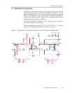
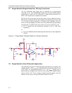
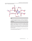
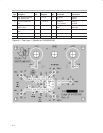
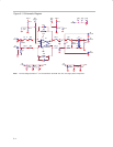
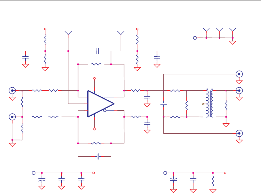
Figure 5−3. Schematic Diagram
C2 0
VCC+
C4
*
R17
0
R8
340
Ω
R5
392
Ω
R13
*
C10
*
R3
402
Ω
−
Vocm
+
U1
THS4503
1
8
2
3
6
5
4
J8
+VS
T1
ADP4−1WT
6 1
5
4 3
R2
374
Ω
TP1
Vocm
+VS
−VS
J6
Vin+
R12
*
J1
Vin−
C12
0.1
µ
F
TP4
C5
*
TP5
R11
*
R16
*
R4
392
Ω
J4
Vout
−VS
C3
*
R14
*
R15
*
C7
*
+
C8
6.8
µ
F
C1 0
J2
Vout+
+VS
J3
Vout−
R7 0
C6
*
TP2
PD−
J5
−VS
VCC+
R1
56.2
Ω
J7
GND
C13
1
µ
F
R9
340
Ω
R10
280
Ω
TP3
C9
0.1
µ
F
+
C11
6.8
µ
F
C14
*
R6 0
Note: Devices designated with an * are not installed on the EVM. The user must supply these components.