Single-Ended In/Single-Ended Out, Utilizing Transformer
3-2
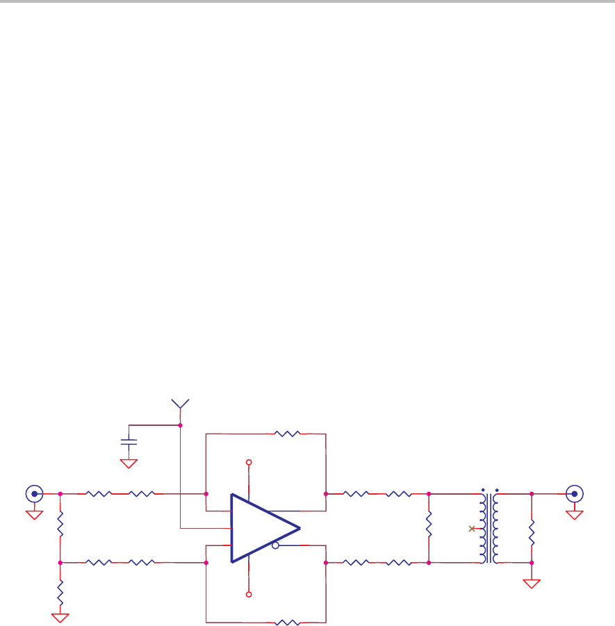
3.1 Single-Ended In/Single-Ended Out, Utilizing Transformer
The fully differential amp output can be monitored by a single-ended
instrument at J4. The THS4503EVM utilizes Mini-Circuits CD542 footprint
transformers to make the fully differential to single-ended conversion. An
ADP4−1WT transformer is installed on the board.
R8, R9, and R10 are chosen such that the load on the fully differential amp is
800 Ω when combined with the load impedance transformed by the turn ratio
T1. This load is chosen because it is a common input impedance value for
ADCs, and is the impedance at which many fully differential amp parameters
are measured. The 800-Ω load occurs when one of two conditions is met:
- R11 is installed and the measuring instrument is set to 1-MΩ input
impedance
or
- R11 is not installed and the measuring instrument has an input impedance
of 50 Ω.
Figure 3−1. Single-Ended In/Single-Ended Out, Utilizing Transformer
R7 0
R2
374
Ω
R5
392
Ω
+VS
R9
340
Ω
R6 0
J1
Vin−
R3
402
Ω
R1
56.2
Ω
R4
392
Ω
R17
0
R10
280
Ω
J4
Vout
R11
49.9
Ω
R8
340
Ω
−VS
−
Vocm
+
U1
THS4503
1
8
2
3
6
5
4
TP1
Vocm
C1 0
T1
ADP4−1WT
6 1
5
4 3
C2 0
C13
1
µ
F
3.2 Single-Ended to Fully Differential Application
The schematic of Figure 3−2 shows the proper technique for ac-coupling. The
voltage present on the V
OCM
pin determines the dc operating point of the
circuit. When no voltage is connected to TP1, the V
OCM
voltage level is
determined by a voltage divider internal to the op amp, and is approximately
equal to half of +VS. This dc voltage is present on both outputs, and also
present on both inputs—being connected through R2 and R3.


