


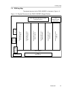


PWM Interface (J100)
2-5
System Interfaces
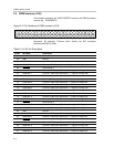
Table 2–4. J100 Pin Description (Continued)
Pin No. Net Name Description
28 PWM–AM–5 Channel 5 PWM input (differential –) – positive H-bridge side
29 VALID–5 Valid channel 5
30 PWM–BM–5 Channel 5 PWM input (differential –) – negative H-bridge side
31 PWM–BP–5 Channel 5 PWM input (differential +) – negative H-bridge side
32 GND Ground
33 PWM–AP–6 Channel 6 PWM input (differential +) – positive H-bridge side
34 PWM–AM–6 Channel 6 PWM input (differential –) – positive H-bridge side
35 VALID–6 Valid channel 6
36 PWM–BM–6 Channel 6 PWM input (differential –) – negative H-bridge side
37 PWM–BP–6 Channel 6 PWM input (differential +) – negative H-bridge side
38 SD–E1 Shutdown group 1 (center + left and right front speakers)
39 SD–E2 Shutdown group 2 (subwoofer + left and right rear speakers)
40 ERROR0 Error signal ERR0 from TAS5110
41 ERROR1 Error signal ERR1 from TAS5110
42 RESET System reset (bidirectional)
43 PSU–COMP–2 For future use
44 PSU–COMP–1 For future use
45 Not Used For future use
46 Not Used For future use
47 +3.3V 3.3-V supply voltage for the modulator module (e.g., the TAS5026REF)
48 GND Ground
49 +5V 5-V supply voltage
50 +5V 5-V supply voltage