


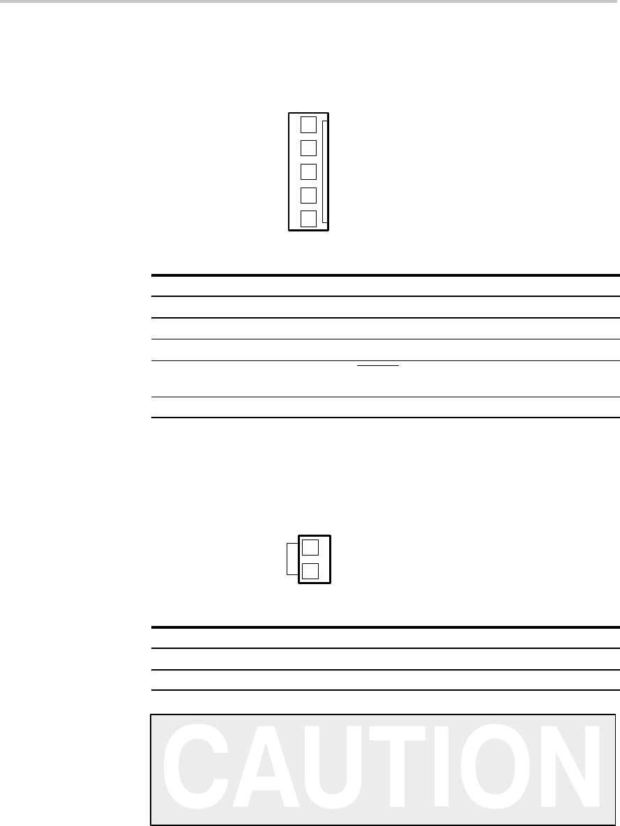
PSU Control Interface (J160)
2-3
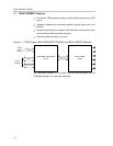
System Interfaces
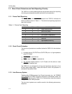
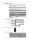
2.2 PSU Control Interface (J160)
This interface is not used in this board.
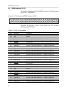
Figure 2–3. Pin Numbers at the PSU Control Interface
1
2
3
5
4
Table 2–2.PSU Control Interface Pin Connections
Pin No. Pin Description Net Name at TAS5110D6REF Schematic
1 For future use
2 For future use
3 Ground GND
4 System reset
(bidirectional)
RESET
5 For future use V-HBRIDGE-CONTROL
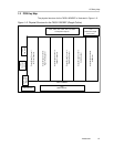
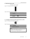
2.3 Loudspeaker Connectors (J240, J280, J340, J380, J440, and J480)
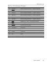
Figure 2–4. Pin Numbers at the Loudspeaker Connectors
1
2
Table 2–3.Description of Loudspeaker Connectors
Pin No. Pin Description
2 Speaker positive output terminal
1 Speaker negative output terminal
Caution
Both positive and negative speaker outputs are floating and may not be
connected to ground (e.g., through an oscilloscope).